An LED is considered as the semiconductor light resource which produces light when there is current flow through the device. The color of the emitted light is known by the amount of energy needed for the electrons to traverse through the semiconductor’s bandgap. Initial LEDs were employed as indicator lamps in the place of incandescent bulbs. Whereas the modern advancements in LED have emitted high-level output appropriate for lighting in external locations. The development of LEDs led to modern sensors and displays where their increased switching rates are helpful in modern-day communication systems. Now, this article focuses on RGB LED, how does it work, schematic diagram, and types.
What is an RGB LED?
RGB LED is fundamentally considered an LED package that holds the ability to emit almost any of the colors. The implementation of this device can be found in many applications like external lighting such as stage, outdoor location, home décor, matrix display, and many others. RGB LEDs consist of three principle-colored LEDs which are Red, Green & Blue. These three colors are combined to emit almost any of the desired colors.
To generate various colors, it is required to set up the intensity level of every internal LED and then combine to get the desired colors. The intensity of every LED can be adjusted by using the PWM procedure and it has noted that even though LED generates individual colors our eyes might see a combination of colors because every color is close to each other and that appears as a mix of colors.
Structure and Types
As it was already stated that RGB LED consists of three individual LEDs and these LEDs share anode or cathode in common particularly in a through-hole kind of package.
The LED consists of four leads where three of the leads are used for their own and the fourth one is used as either a common cathode or anode. Every lead in the LED is identified by its length. The structure is shown below:
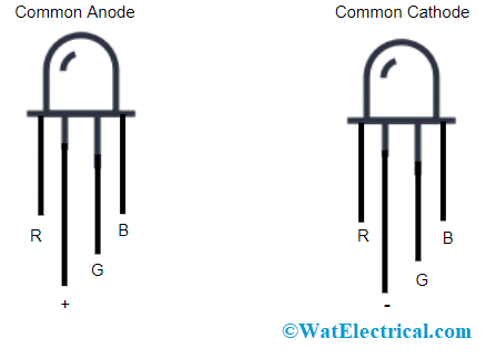
RGB LEB Structure
Assume that the lead is facing towards you and in this direction, the lengthy lead which is second from the left position is either anode or cathode and then the sequence follows as red, anode/cathode, green and blue.
This is how the RGB LED structure looks like. When one is not able to distinguish between anode and cathode by its length, then it can be possible through a multimeter. The procedure for this is explained below:
- Place the multimeter in continuity mode
- Put the multimeter tip which is red in color on the lengthy lead and the other tip of the multimeter (black colored tip) on any one of the other leads.
- When the LED emits light, this indicates that the long lead is a common anode.
- In the same way, place the multimeter tip which is black in color on the lengthy lead and the other tip of the multimeter (red-colored tip) on any one of the other leads. When the light emits, then the lengthy red is considered a common cathode.
In regard to this discussion, there are mainly two RGD LED types which are
- Common Anode
- Common Cathode
Let us discuss each of these in detail in the below sections.
Common Anode
- In this type of RGB LED, the anode part of all the internal LEDs are connected together and this is connected to the lead of the external anode. In order to control every color, the connection should be like below:
- A LOW or ground signal should be applied for Red, Green, and Blue lead.
- Connect the anode to the power supply’s positive terminal.
The connection of common anode LED type is shown below:
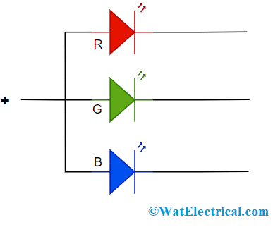
RGB LED Common Anode Pinout
Common Cathode
- In this type of RGB LED, the cathode part of all the internal LEDs are connected together and this is connected to the lead of the external cathode. In order to control every color, the connection should be like below:
- A HIGH or Vcc signal should be applied for Red, Green, and Blue leads.
- Connect the anode to the power supply’s negative terminal.
The connection of common cathode LED type is shown below:
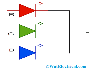
RGB LED Common Cathode Pinout
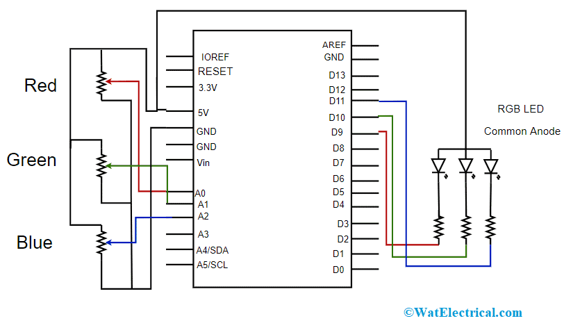
Setting the Color of an RGB LED using an Arduino Uno
To set up the color of an RGB LED, the essential components those are required are:
- One Arduino Uno unit
- Jumper wires
- RGB LED with the common cathode lead
- Resistors of 100Ω – 3 units
- Trimmers/Potentiometers of 1kΩ- 3 units
To obtain the required color from RGB LED, it is needed to set the intensity level of every internal LED. To achieve this, either PWM (pulse width modulation) or CCR (constant current reduction) techniques can be employed. Here, the PWM technique is used because Arduino Uno is used for setting up the color.
The arrangement and design can be done easily. The RGB LED with common cathode, potentiometers, resistors, and Arduino Uno board are connected together through jumper wires. The connection is done in the way that three potentiometers are connected A0, A1, and A2 ADC channels of the Arduino unit. This ADC unit measures the level of analog voltage that is across the wiper edge of the trimmer. And depending on the voltage, the Arduino sets up the duty cycle of the signals in PWM that are produced at the pins D9, D10, and D11.
Here, is the pin configuration of the Arduino Uno board.
The Arduino Uno is included with 6 pins for analog input, a 16MHz resonator, power jack, reset button, ICSP header pin, USB pin, and 14 pins for digital i/p and o/p. The supply voltage for the IC is 12V. The pin description is explained below:
- RESET pin – RST is used to reset the microcontroller
- TWI pins – Useful for communication which are A4 and A5
- LED pin – When the LED pin is high, the LED glows which is pin 13
- Pin 2 and 3 – These are external interrupt pins that get activated when the clock is at either HIGH or LOW
- Pins 3, 5, 6, 9, 10 & 11 – These are PWM pins and the output from these pins are in 8-bit format
- Pins 10, 11, 12 & 13 – These are SPI pins
- AREF pin – This is the voltage reference pin
- Serial pins – The pins RX0 and TX1 are used for communication for data transfer between peripherals
- Memory – This consists of 32KB memory along with 2KB SRAM and 1KB EEPROM
Schematic Diagram of RGB LED
The schematic diagram can be drawn in two ways for the common anode and common cathode. The difference between these two wirings lies in the second lead. In the case of the common anode, the 2nd pin is connected to the 5V pin of the board whereas, for the common cathode, the 2nd pin is connected to the GND pin. To have a clear understanding, a software sketch is useful. So, by running the sketch/code, the color of the RGB LED can be known.
The common anode schematic diagram is
Schematic Diagram for Common Anode
The schematic diagram for the common cathode is
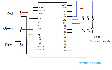
Schematic Diagram for Common Cathode
Advantages and Disadvantages
The benefits and drawbacks of RGB LED are:
Advantages
- Minimal device size
- Less toxicity
- When compared with normal LED, the brightness and contrast levels of RBG LED are better
- Delivers good efficiency
Disadvantages
- Designing cost is more
- Shows color dispersion
- It has shifted in color
So, RGB LED is simple to understand and design. This article has clearly explained how RGB LED works, its schematic diagram, set up using Arduino Uno, and its Types. Know how to write Arduino Uno and upload it into the board using Arduino IDE.