A power electronic device that is used to change power from DC to AC form at the necessary frequency & voltage output is known as an inverter. The inverter input is a fixed DC voltage that is attained from the batteries & the inverter output is normally a variable or fixed frequency alternating voltage. The inverter is designed as separate equipment to use in different applications. Inverters are available in different types based on the switching waveform shape, configurations of the circuit, efficiencies, benefits, and drawbacks. But generally, these are classified into two types like single phase inverter and three phase inverter. This article provides brief information on single-phase inverter, their working, and their applications.
What is a Single-phase Inverter?
A kind of DC-to-AC inverter used to change DC input power to 1-phase AC output power at preferred voltage &frequency is known as single phase inverter. These types of inverters are most frequently used in small commercial & residential applications. The main difference between single and three phases are; single phase produces single-phase power using Photo Voltaic modules and this power can be used for a grid or single-phase equipment. A three-phase changes the DC input into a three-phase AC output.
A phase is a current or voltage that will exist between a presently used wire & a neutral cable. A single-phase needs two wires which have significantly low power whereas a three-phase will have a minimum of three or four wires.
Single Phase Inverter Working Principle
A single-phase inverter simply works by changing a DC i/p, frequently sourced from a fuel cell/ battery into an AC o/p through a switching process. The fundamental working principle of this inverter is to use the DC i/p voltage to switch the o/p voltage in between positive & negative values at a preferred frequency. To design this inverter, there are several ways although most utilize some type of switching device for achieving the voltage inversion.
In these types of inverters, the most commonly used switching devices are integrated circuits or transistors which are controlled through a control circuit like a simple timer or a complex microcontroller-based circuits.
This circuit produces the switching signals to turn ON & OFF the device. After that, the output of the inverter is filtered to eliminate any noise or remaining ripple which is fed to the electrical load. Here, the load can be any device like a lighting system, household appliance, or a motor that needs AC. A single-phase inverter is very useful in a wide range of applications like backup power supplies, portable power tools & renewable energy systems.
Single-phase inverters are ideal for use in home appliances, power tools, office equipment, portable equipment, lighting, heating, water pumping in agriculture, adjustable speed AC drives, induction heating, vehicles, UPS, and grid-connected applications.
Single-Phase Inverter Types
Single-phase inverters are two types; half bridge inverter and full bridge inverter which are discussed below.
Single Phase Half-Bridge Inverter
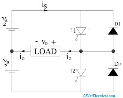
The single-phase half-bridge inverter circuit diagram is shown below. This circuit is designed with thyristors as well as diodes with a dc power input source. The T1 thyristor in this circuit conducts mainly for half of the time period whereas the T2 thyristor conducts simply for the rest of the time period in the o/p waveform. In this circuit, the diodes like D1 and D2 connected are anti-parallel by the thyristor and that allows the flow of current once the main thyristor is turned off.
Single Phase Half-Bridge Inverter
When the voltage is positive and the current is negative then the first diode conducts and the second diode conducts when the current is positive and the voltage is negative. So it is particularly helpful in the case of non-resistive loads. These diodes are known as flyback diodes because whenever the diode conducts the energy will fed back to the source of DC.
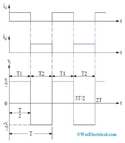
In this circuit, each thyristor is activated through its gate terminal. Once the circuit is analyzed, it is understood that every thyristor conducts for the period of its present gate pulse & is commutated once this pulse is detached. In the following figure, the thyristor’s gating signals (ig1 & ig2) and the inverter’s output voltage waveform are shown.
Here we can notice that, if the gating signal is applied for 0 < t ≤ (T/2) period, then the T1 thyristor will conduct & the load is connected directly to the Vs/2 source on the higher arm of the circuit & the o/p voltage equals ‘Vs/2’ throughout this time.
At time ‘T/2’, when the ig1 gating signal is removed, the T1 thyristor will be turned off and when the ig2 gate signal is applied, the T2 thyristor will start conducting. After that, the load is directly connected to the -Vs/2’ on the lower arm. Now the o/p voltage is ‘-Vs/2’ as given in the below waveform. The resulting o/p waveform is an alternating square wave through a 1/T Hz frequency & a Vs/2 amplitude. The frequency can be controlled by simply changing the time period ‘T’ value.
Single Phase Half-Bridge Inverter Waveforms
Single Phase Full-Bridge Inverter
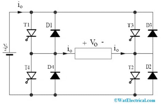
The single-phase full-bridge inverter with a load circuit diagram is shown below: This circuit is designed with four thyristors indicated with a two-wire DC source, T1 to T4, four diodes D1 to D4 & a load. In this circuit, the four diodes are simply connected to four thyristors anti-parallel so that they let the flow of current once the main thyristor is deactivated. Once these four diodes conduct, then energy is fed back to the DC source and hence, these diodes (D1 to D4) are called flyback diodes. It is assumed that each of the thyristors only conducts for the period its gate signal is present and as soon as the gate signal is removed, the thyristors get turned OFF.
Single Phase Full-Bridge Inverter
The four thyristors in the circuit are diagonally activated. First T3 and T4 thyristors will be turned ON for half of the time period whereas T1 and T2 thyristors will be turned ON for the remaining time period. So in half of the time period, only two thyristors will be turned ON.
The sequence of thyristors turn on is given as’
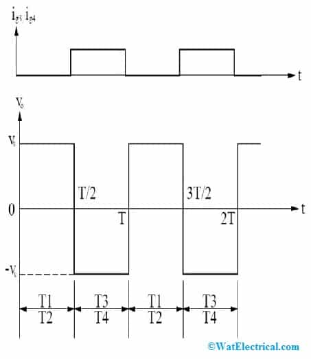
The T1 and T2 thyristors will conduct for the 0 < t≤ (T/2) time & the load voltage will be Vo = Vs.
The T3 and T4 thyristors will conduct for the (T/2) <t≤ T time & the load voltage will be Vo = -Vs.
The gate signal & the waveforms for the output voltage are given below:
Full-Bridge Inverter Waveforms
The T1 & T2 thyristors are triggered simultaneously for a T/2 time. So, the load is connected to the source through T1 & T2, and hence, the load voltage is equal to the source voltage with positive polarity. As soon as the gate signals (ig1 & ig2) are removed, T1 and T2 gest are turned OFF. However, at the same instant gate signals (ig3 & ig4) are applied and hence, T3 & T4 are turned ON. When T3 & T4 are conducting, the load gets connected to the source. The load voltage magnitude is again Vs but with reverse polarity.
Single Phase Inverter Using Arduino
The single-phase inverter with an Arduino circuit is designed with an Arduino board and a few MOSFETs in the circuit. Here single phase inverter used is the full-bridge or h-bridge inverter.
The required components to make this circuit are; Arduino Uno, 4093 NAND gate IC, 24V/100Ah battery, 7812 voltage regulator, IRF9540 MOSFETs -2, IRF540 MOSFETs -2, transformer, and 0.1uF capacitor. Connect the circuit as per the circuit diagram shown below.
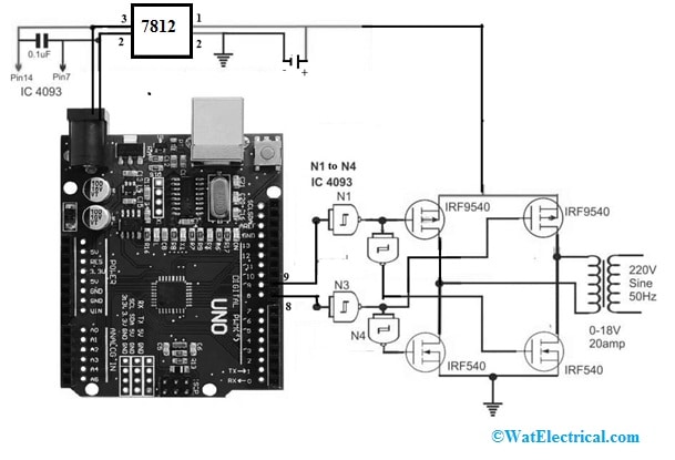
Single Phase Inverter Circuit using Arduino
This circuit is designed with the P-channel MOSFETs at the high side and N-channel MOSFETs at the low side so that it allows us to evade the complex bootstrap stage & permit the Arduino signal integration with the MOSFETs directly. Generally in full bridge-based inverters, N-channel MOSFETs are used to make sure the most perfect current switching across the MOSFETS & the load, and guarantees very secure mosfets working conditions.
Once p-channel & n-channel mosfets are used, then there is a risk of a shoot & both the MOSFET’s similar factors will become an issue. So, mosfets blowing can be avoided if the transition phases are correctly protected through a small dead time, then switching can be made very safe.
In this circuit, IC 4093 NAND gates (N1 to N4) are used to ensure that the switching across the two channels is not affected by any type of low signal disturbance or spurious transients.
The logic operation of N1 to N4 logic gates are;
Whenever Pin-9 of Arduino is logic 1 & pin-8 is logic 0 then;
The output of N1 AND gate is 0, the p-MOSFET at top left is ON, N2 AND gate output is 1, then n-MOSFET at lower right will be ON.
The output of N3 AND gate is 1, the p-MOSFET at top right is OFF, N4 AND gate output is 0, then n-MOSFET at the lower left side will be OFF.
For the other MOSFETs which are connected diagonally, the same sequence happens once pin-9 is logic 0 & pin-8 is logic 1.
Working
The working of this circuit follows as; Arduino uno is programmed to generate formatted SPWM outputs appropriately from pins 8 & 9. When one of these pins generates the SPWMs, then the complementary pin will held low. SPWM (sine wave pulse width modulation) is a kind of pulse modulation wherever the pulses are changed to reproduce a sinusoidal waveform, thus the modulation is capable of attaining pure sine wave properties.
The outputs from the pinouts of Arduino can be processed throughout N1 to N4 NAND gates from the 4093 IC. All these NAND logic gates are arranged like inverters through a Schmidt response & fed to the significant MOSFETs in a full bridge driver network.
Whenever pin9 of Arduino generates the SPWMs, then the N1 NAND gate inverts the SPWMs & ensures the significant high side mosfets react & conduct to the high SPWM logics, and the N2 NAND gate ensures the N-channel mosfet at the low side.
During this, pin-8 of Arduino is held at logic zero, which is interpreted appropriately through N3 & N4 logic gates to make sure that the other opposite MOSFET pair in the H-bridge circuit will stay totally switched OFF. The above criteria can be repeated identically once the generation of SPWM transmits to pin8 from pin9. The set conditions are constantly repeated across the pinouts of Arduino & the pairs of full bridges.
Code
void setup(){
pinMode(8, OUTPUT);
pinMode(9, OUTPUT);
}
void loop(){
digitalWrite(8, HIGH);
delayMicroseconds(500);
digitalWrite(8, LOW);
delayMicroseconds(500);
digitalWrite(8, HIGH);
delayMicroseconds(750);
digitalWrite(8, LOW);
delayMicroseconds(500);
digitalWrite(8, HIGH);
delayMicroseconds(1250);
digitalWrite(8, LOW);
delayMicroseconds(500);
digitalWrite(8, HIGH);
delayMicroseconds(2000);
digitalWrite(8, LOW);
delayMicroseconds(500);
digitalWrite(8, HIGH);
delayMicroseconds(1250);
digitalWrite(8, LOW);
delayMicroseconds(500);
digitalWrite(8, HIGH);
delayMicroseconds(750);
digitalWrite(8, LOW);
delayMicroseconds(500);
digitalWrite(8, HIGH);
delayMicroseconds(500);
digitalWrite(8, LOW);
//……
digitalWrite(9, HIGH);
delayMicroseconds(500);
digitalWrite(9, LOW);
delayMicroseconds(500);
digitalWrite(9, HIGH);
delayMicroseconds(750);
digitalWrite(9, LOW);
delayMicroseconds(500);
digitalWrite(9, HIGH);
delayMicroseconds(1250);
digitalWrite(9, LOW);
delayMicroseconds(500);
digitalWrite(9, HIGH);
delayMicroseconds(2000);
digitalWrite(9, LOW);
delayMicroseconds(500);
digitalWrite(9, HIGH);
delayMicroseconds(1250);
digitalWrite(9, LOW);
delayMicroseconds(500);
digitalWrite(9, HIGH);
delayMicroseconds(750);
digitalWrite(9, LOW);
delayMicroseconds(500);
digitalWrite(9, HIGH);
delayMicroseconds(500);
digitalWrite(9, LOW);
}
What is the Single Phase?
Single-phase is a two-wire AC power circuit that includes a single power wire (phase wire) & single neutral wire by the flow of current between the power wire & the neutral wire.
What is a single-phase rectifier?
A rectifier that uses single-phase AC voltage to deliver the output DC voltage which is fixed is known as a single-phase rectifier.
What is the most efficient type of single-phase rectifier?
The most efficient type of single-phase rectifier is a full-wave rectifier or FWR because it utilizes input sine wave in both half-cycles for generating an equivalent or higher average DC o/p voltage.
What is the single-phase inverter output voltage formula?
The o/p peak voltage in the full bridge inverter is equivalent to the i/p DC voltage (VDC) which is lowered by the drop of voltage on the two switching transistors (Von). So Vout peak = VDC- 2Von. Similarly, the input voltage ‘VDC’ in a half-bridge inverter can be separated into equivalent parts.
Advantages and Disadvantages
The advantages of single phase inverter include the following.
- Single-phase inverters are cost-effective, small & very easy to install.
- Its installation is very simple.
- These inverters are perfect for homes.
- These types of inverters are compact & lightweight.
- The current that is supplied throughout the wires is low as compared to the voltage transmitted is high.
- These are noiseless while operating.
- These are durable, efficient, and also more eco-friendly.
- They are powered by battery, so they are very simple to reinstall & dismantle.
- These inverters are built durably & last much longer as compared to other kinds of home backup systems.
Applications
The applications of single-phase inverters include the following
- These types of inverters are suitable for use within power tools, home appliances, office equipment, lighting, heating, portable equipment, adjustable speed AC drives, water pumping in agriculture, induction heating, vehicles, grid-connected applications & UPS.
- These inverters are used in some industrial applications which include AC drive speed adjustment, aircraft power supplies, HVDC transmission lines, and many more.
- These are used to adjust the speed of a small power electric motor.
Thus, this is an overview of a single-phase inverter, its types, working, and its applications. This is a type of Inverter used to change DC input to 1-phase AC o/p at preferred voltage & frequency. Here is a question for you, What is a three-phase inverter?