An inverter is one of the most frequently used electronic circuits in most of the applications. It’s a circuit that converts fixed DC supply to alternating AC supply to feed AC loads. Widely used in commercial, aviation, residential and industrial applications. It could be regarded as the backbone for most of the applications. It is frequently used as an interfacing unit between DC supply and load. In many cases, it acts as an interfacing unit between AC supply and load also. For example, in the speed control of induction motor, the supply is AC, but AC supply is converted to DC by a rectifier circuit and again DC is converted to AC by inverter and fed to the induction motor. It helps to improve power quality by overcoming the harmonic content.
What is an Inverter?
Definition: The inverter is an electronic circuit that converts fixed DC supply to variable AC supply. The inverter is used to run the AC loads through a battery or control AC loads via AC-DC conversion. Inverters are also available as single-phase inverter and three-phase inverters. Of course, in three-phase inverter more switching operations are required. Let see the circuit diagram and working principle of single-phase and three-phase inverters.
Single Phase Inverter
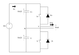
A single-phase inverter or also called as half-bridge inverters, converters DC supply to single-phase AC supply. For this purpose, two switching devices are used to convert DC to AC. Diodes, capacitors help the circuit to operate smoothly.
Single-phase Inverter Working Principle
As the name implies, half-bridge inverter, the output varies from +Vs/2 to -Vs/2. As shown in the circuit, two switching devices are connected in one common branch or also called a leg. This switching may be SCR, MOSFET, or IGBT. Generally, we use MOSFET more commonly for high-frequency applications. One more advantage with MOSFET is it has low switching losses but high conduction losses.
Single Phase Inverter
As shown in the circuit, we have two switching devices S1 and S2. To obtain one cycle of Alternating voltage, each device is triggered at one time. The other being off at the same moment. For example, to obtain the positive cycle of Alternating supply, device S1 is turned on, while S2 is kept off. Similarly to obtain a negative cycle of alternating supply, device S2 is turned on while S1 is kept off. The output wave is shown as below.
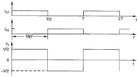
Output Voltage Waveform Half Bridge
As shown in the output figure, when S1 is conducting from 0 to T/2 the output +Vs/2 is obtained. Similarly, when S2 is conducting from T/2 to T, the output -Vs/2 is obtained. Hence the output alternates between +Vs/2 to -Vs/2, which is regarded as alternating voltage. T is the total time period of the conduction of two devices. It can be noted that the output voltage waveform is a stepped square waveform. In inverters, we never obtain a sinusoidal waveform. The stepped square waveform alternates between two values, which is considered as alternating voltage. The same is for three-phase inverter also.
Please refer to this link to know more Single Phase Inverter MCQs.
Three Phase Inverter
As shown in the circuit diagram, it is a three-phase inverter, also called a full-bridge inverter. In all for the circuit, we require six switching devices. From a DC supply, we obtain a three-phase alternating voltage on the load side.
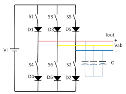
Three Phase Inverter Circuit Diagram
Three-phase Inverter Working Principle
Firstly, the devices need to be numbered for the correct operation. Note that, we have six devices, two devices on one leg. This circuit is also called as three leg operation. There is a logic behind the numbering of the devices. The devices are numbered as per the sequence of triggering. This means that as shown in the circuit, the switch S2 is triggered after S1, and similarly for the rest of the devices. The output required is three-phase voltage, which means that three-phase sequences, separated by 120 degrees each are required. For each phase sequence, one pair of switching devices are operated. This means that to obtain the R phase, S1-S2 is turned on. To obtain Y phase S3-S4 are turned on and to obtain B phase S5-S6 are turned on. The output waveform is shown below.
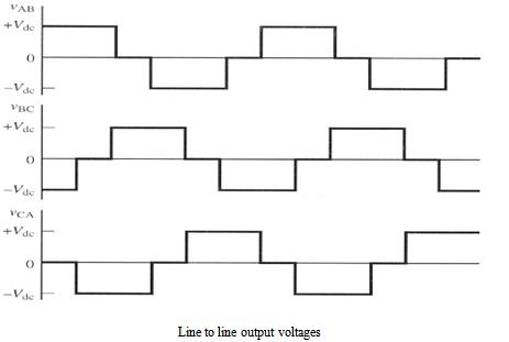
Three Phase Inverter Output Voltage
As shown in the circuit, we obtain a stepped square waveform. One important thing to be noted is, there should be a time delay between the firing of one device and the other. For example, when we obtain the R phase we trigger S1 and S2. S1, S2 are not fired at the same time. There is a delay of 60 degrees. However, each device may be a diode or MOSFET conducts for 120 degrees. Again the time of conduction and instant of triggering varies on the mode of conduction also. We have two modes, 180-degree one is a mode of conduction and 120-degree mode of conduction. The fundamental difference is in 120 degrees of conduction, a deliberated delay of 60 degrees is given for each device to avoid short circuit of two devices.
Applications
The applications of inverters include the industry, residential, etc. It is one of the most frequently used devices. A few applications have been described in brief
- Uninterruptable Power Supply (UPS) – These are commonly used circuits in computer systems. To avoid abrupt disconnection of supply to computer systems, computers are given supply via UPS.
- Electric Motor Speed Control – In this application, the AC supply is converted to DC by a rectifier, and again DC is converted to AC by inverter. This helps to obtain variable AC from a fixed DC. At the load side, we can obtain varying AC to control the speed of the motor ( Armature voltage control)
- Refrigeration Compressors – In this, it used to control the speed of compressor motor drive for variable refrigeration.
- High Voltage DC Systems (HVDC) – In this for transmitting power for long distances the AC power is a converter to DC, transmitted, and again DC is converted back to AC with the help of inverters. This conversion is necessary to overcome stability problems in AC transmission.
- Solar Photovoltaic Cells (PV Array) – One of the most recent technologies in view of renewable energy conversion. Here the sunlight energy is used to produce electric energy by using solar cells. Solar cells produce DC which is again converted to AC using inverters.
Other commonly used applications are induction heating, power grid, storage of energy, etc.
How to Make an Inverter?
A single-phase inverter can be easily built even at home also. This requires a battery, to MOSFETS, an AC load, and connecting wires. As shown in the figure for single-phase inverter, it can be easily connected to obtain a variable AC supply.
FAQs
1). What is the difference between UPS and inverter?
UPS or uninterruptable power supply is basically used to store energy by using batteries. But inverters are used to convert DC supply to AC for control or supplying AC loads. A combination of UPS and inverters forms the commercial UPS sold in the market.
2). Which is dangerous, AC, or DC?
Keeping in view of magnitude, DC is more dangerous than AC. AC alternates its magnitude, but DC is a fixed value.
3). What will a 3000 W inverter run?
With a 3000 W inverter many applications at home such as two fans, three tube lights, TV, computer system, etc. can be easily run for 3-4 hours. However heavy loads such as Air conditioner, fridge, etc needs to be avoided.
4). How many amperes does an inverter draw?
Ans. The calculation is simple. Power is given as the product of voltage and current. So a 300 W, 15V inverter can draw up to 20 A. However keeping the losses in mind, the values are less.
5). What is dual inverter technology?
A Dual inverter AC is an advanced technology which houses twin rotary compressor which can give a more efficient performance with less noise. The provision of twin rotary compressors improves rotor balancing and compression torques.
Know more about Three Phase Inverter.
We have seen the circuit diagram, working principle of single-phase and three-phase inverters along with waveforms. We have also seen the applications and features of inverters. One recent advancement in the control of AC loads using inverters is pulse width modulation of the output stepped square waveform. This provides efficient and precise control of speed for induction motors. One may think over the fact that what is the fundamental difference between sinusoidal pulse width modulation and space vector pulse width modulation?