In an electrical circuit, there are two kinds of systems available; 1-phase (single phase) & 3-phase (three phase). In a 1-phase circuit, the flow of current will be only a single wire and also a neutral line to complete the electrical circuit thus, the least amount of power can be transmitted within a single phase. Here the generating station and load station will also be single phase. In the year 1882, a new development was done on the polyphase circuit that is, more than one phase can be utilized to generate, transmit, and load a system known as a three-phase system where 3-phases are transmitted jointly from the generator to the electric load. This article discusses an overview of a three-phase system, it’s working & its applications.
What is a Three Phase System?
The system which uses three wires to generate, transmit and distribute power is called a three-phase system. This system uses three phases so that the current will supply through three wires. From these three wires, there will be a neutral wire that supplies fault current toward the earth. This type of system can also be used as a one-phase system by extracting one of the phases & the neutral wire from them. In this system, the amount of the line current is equivalent to zero & their phases are simply distinguished at a 120º angle.
This system will be induced within the generator to provide the three-phase voltage of equivalent frequency & magnitude. So it provides continuous power which means if the system’s one phase is interrupted then the remaining two system phases will supply the power uninterruptedly. In a single phase, the current magnitude is equivalent to the amount of current within the other two phases of the system. For proper system working, the phase difference with 0 degrees is a must, or else the system will get damaged.
Types of Connections in Three-Phase System
In a three-phase system, there are two types of connections possible like star and delta which are discussed below.
Star Connection
Star connection is one type of connection in this system which is also called a 3-phase 4-wire system and it is denoted with ‘Y’. This connection is most frequently used for the distribution of AC power. The star connection can be formed by connecting the beginning or finishing ends of three coils to make the neutral point & the other ends are simply connected to the line wires. In this connection, the common point is known as a star or neutral point denoted by N.
This connection includes four wires where three wires are known as phase wires & remaining wire is a neutral wire that is taken from the neutral point. This type of connection is mostly used for power transmission over long distances because it has a neutral point. In a three-phase system, when the current flows equally in all three phases then it is known as a balanced current. When the current in any of the phases will not flow equally, then it is called an unbalanced current.
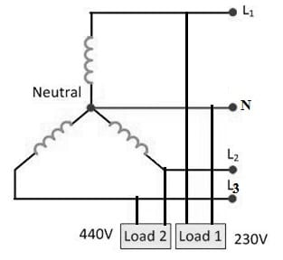
Star Connection in Three Phase System
In a balanced condition case, there is no current flow throughout the neutral line, so there is no utilization of the neutral terminal. However, when an unbalanced current flows within the three-phase circuit, then the neutral wire plays a key role by passing the unbalanced current toward the earth & makes the three-phase system balance.
The three-phase system in star connection provides two different voltages like the 230Volts & 440Volts. The voltage between the 1-phase & the neutral wire is 230V & the voltage between the 2-phases is equivalent to the 440Volts.
Delta Connection
In 3- phase system, Delta connection is one type of connection, denoted with ‘Δ’. This connection is also called a Mesh connection. The delta connection in three phase system can be formed by connecting one winding’s last terminal to the starting terminal of the other winding & so on to provide a closed circuit. Here, the 3-line conductors are run from the 3 junctions of the mesh known as line conductors.
This type of connection includes 3 wires & there is no neutral wire is in use. Generally, this type of connection is chosen mostly for short distances because of the unbalanced current problem within the circuit. In this connection, the line voltage is equal to the phase voltage.
As shown in the above delta connection, a2 is connected with b1, b2, and b1, b2 is connected with c1 c2 & c1 c2 is connected with a1. The R, Y & B in the above connection are three conductors which run from the 3-junctions called line conductors. The flow of current through every phase is known as Phase Current denoted by ‘Iph’ & the flow of current throughout every line conductor is known as Line Current, denoted by ‘IL’.
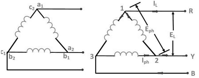
Three Phase System Delta Connection
The loads in a three-phase system can be connected either in a star or delta connection. The 3 phase load may be unbalanced or balanced. If the 3 loads have a similar phase angle & magnitude then the – phase load is known as balanced load. In balanced conditions, the three phases as well as the line voltages are equivalent within magnitude.
What is Split-Phase Power System?
A split-phase power system is one type of 1-phase electric power distribution which is also called a 1-phase 3-wire system. This system is the AC equivalent for the innovative Edison machine works 3-wire DC system. This system includes multiple AC voltage sources which are connected in series, for transmitting power to the loads at above one voltage using above two wires. These systems are mainly used to attain a balance between the efficiency of the system & safety. The main benefit of this system is that, for a specified distribution system capacity, it simply saves the material of the conductor above a single-ended 1-phase system when requires a single phase only on the distribution transformer supply.
These power systems are very common for residential as well as light commercial-based applications in North America. These systems are also used for decreasing the electric shock risk and also to decrease electromagnetic noise.
Phase Sequence in Three-Phase System
In 3-phase systems, the order in which the voltages achieve their highest positive value is known as phase sequence. In the 3-phase system, there are 3 voltages or EMFs by equal magnitude, although the frequency is shifted by 120 degrees angle electrically.
For instance, in any coil, the phases are indicated with R, Y & B then the +ve phase series will be clockwise like RYB, YBR, and BRY. Likewise, the -ve phase series will be anti-clockwise like RBY, BYR & YRB respectively.
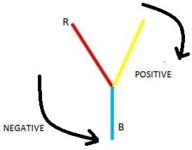
Phase Sequence in Three-Phase System
In three phase system, phase sequence is very significant due to many reasons.
- The 3-phase transformer’s or alternator’s parallel operation is possible only once its phase series is known.
- The 3-phase induction motor’s rotating direction mainly depends on its phase series on the 3-phase supply & thus the phase series of the supply provided to the motor has to be modified to reverse its direction.
3-Phase EMF Generation in AC Circuits
In a 3-phase system, there are 3 equivalent voltages otherwise the same frequency EMFs with 120 degrees of phase difference. These voltages can be generated through a 3-phase AC generator including equal windings which are moved separately from each other at 120 degrees. Once generator windings are kept inactive & the magnetic field is turned as shown in the below figures A & B, an EMF can be induced in every winding. The EMF’s frequency & magnitude are the same although they are displaced apart from each other at 120 degrees angle.
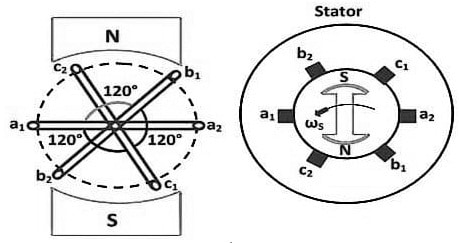
3-Phase AC Generator
In the above figure, we need to consider three equal coils a1a2, b1b2 & c1c2. So in that coils, a1, b1 & c1 are the initial terminals while a2, b2 & c2 are the end terminals of the 3 coils. But in between the a1, b1 & c1 start terminals, the phase difference with 120 degrees has to be maintained.
Now, the three identical coils which we have mentioned above are mounted on a similar axis, & they are turned by keeping the coil inactive & moving the magnetic field in the direction anticlockwise at ‘ω’ radians for each second. In the 3-coils, three EMFs are induced correspondingly.
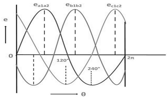
In the above figure, the magnitudes analysis & their directions are provided like the following.
Three Phase EMF
In the a1a2 coil, the induced emf is zero & it is increasing within the +ve direction represented with ea1a2. The induced emf in the b1b2 coil is 120 degrees behind the a1a2 coil. The emf induced in this coil is -ve & is becoming negative utmost as represented with the b1b2 wave. Similarly, coil c1c2 is 120 degrees behind coil b1b2, otherwise, we can also state that the c1c2 coil is 240 degrees behind the a1a2 coil. The induced emf within the coil is +ve and is decreasing as shown in the above figure which is signified by the ec1c2 waveform.
Phasor Diagram
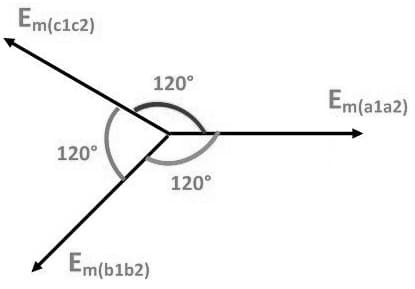
In 3-phase circuits, the induced emf within the 3 coils have similar frequency & magnitude which are relocated with an angle of 120 degrees from each other as illustrated in the following phasor diagram:
Phasor Diagram
The three-phase circuits emfs can be simply expressed in different forms of equations as shown below:
ea1a2 = E0 sin ωt.
eb1b2 = E0 sin (ωt – 2π/3) or E0 sin (ωt – 120o) .
ec1c2 = E0 sin (ωt –240o).
Why is Three Phase Preferred Over a Single Phase?
There are many reasons to prefer three phases instead of a single phase which are discussed below.
- The three-phase system needs fewer conductors as compared to one phase system.
- This system provides supply to the load continuously.
- This system’s efficiency is higher & losses are minimum.
- In this system, the voltage drop that occurred is low from the source terminal to the load.
- The operated machine size of the three-phase system is less.
- A three-phase supply produces a consistent rotating magnetic field so, the construction of three-phase motors is simpler, small in size & can be automatically started with smooth operation.
- This type of system transmits more power.
- The three-phase systems are not expensive.
- These systems provide stable power so it leads to very smooth & vibration-free operation.
- The machine’s o/p rating is increased by simply increasing the no. of phases within a system.
- A three-phase machine occupies less space.
- A 3 phase supply can be changed easily into a one-phase supply.
- If a fault occurs on a single line within three phases then the remaining two lines provide the supply to other connected one-phase load points to them.
- A three-phase motor offers consistent torque.
- The three-phase motors can be started automatically.
- The motors with three phases have a superior power factor.
- If a three-phase motor, alternator, or transformer frame size is similar to a one-phase transformer, alternator, or motor then the output of the three-phase machine is higher as compared to a one-phase machine
Please refer to this link for a three-phase system versus a single-phase system: Phase in Electricity.
Applications
The applications of the three-phase system include the following.
- A three-phase system is directly used for providing power to large induction motors, heavy loads & different electric motors.
- Three-phase power very efficient power source and it is pretty helpful for industrial or commercial applications.
- These types of systems are used for distributing high power to different buildings.
- These are used to drive electric motor equipment.
- Three-phase AC power provides electricity to commercial, industrial buildings & data centers.
Thus, this is an overview of a three-phase system, it’s working, and its applications. From the above information, finally, we can conclude that the 3-phase system has higher & better efficiency than the 1-phase system. Here is a question for you, what is a single-phase system?