The steps began for the introduction of induction motor in the year 1892. Earlier it was made to run under 60 HZ power supply in 1893. This was made practically possible by Westinghouse. Later investigations have been conducted to work these type of motors under two-phase supply. The multi-phase supply produced much better advantages than single-phase. The disadvantage of one-phase is, it cannot self-start while the three-phase motor can self-start. The Three-phase IM can develop a Rotating magnetic field which makes it possible to self-start. In this article, we shall discuss what are the types, construction, working, starting methods, disadvantages, advantages, and applications.
Types of Single-Phase Induction Motor
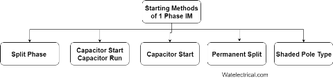
These are classified into different types depending upon the different starting methods. They are
- Split Phase Induction motor
- Capacitor Start Induction motor
- Capacitor Start capacitor-run Induction motor
- Permanent Capacitor
- Shaded Pole type
The required motors are selected depending upon required staring and running torque, starting and running currents drawn from the supply and duty cycle. The Starting methods of one phase IM is shown in the figure below.
Starting Methods
1) Split-Phase
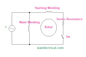
In Split-phase IM, a resistance is connected in series with the starting winding. So, it is also called as resistance-start IM. A switch (SW) is also connected in series with the winding to switch off after the rotor has attained running speed. The main winding and the starting winding or auxiliary winding are displaced at an angle 90 degrees to each other. The split-phase IM is shown in the figure below.
Split Phase Induction Motor
The main winding has low resistance and high reactance whereas the auxiliary winding has high resistance and low reactance value. The winding diagram of the Split Phase IM is shown in the figure below.
Split Phase
The phasor diagram of split-phase IM is shown in the figure.
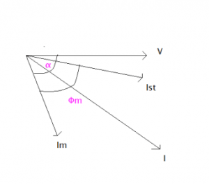
Split Phase Phasor Diagram
From the phasor diagram, we can understand that the main field current lags the voltage by an angle. But due to the starting winding, the starting current phasor angle decreases. It is almost in the phasor with the voltage. So, an initially high starting torque can be developed.
2) Capacitor Start Induction Motor
A capacitor is connected in series with the starting winding associated with a centrifugal switch. This capacitor is used to start the motor initially until it attains sufficient speed, after that the capacitor is disconnected by opening the switch. The capacitor start IM is shown in the figure below.
The winding diagram of the capacitor start IM is shown in the figure below.
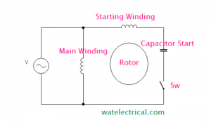
Capacitor Start
The phasor diagram corresponding to the capacitor start motor is shown in the figure below.
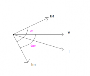
Capacitor Start Phasor Diagram
From the phasor diagram, we can understand that the main field winding will be leading the voltage as it is capacitive nature due to the introduction of a capacitor. The starting torque would be high and with improved power factor. But poor running torque due to the removal of a capacitor using a switch after the rotor initiation.
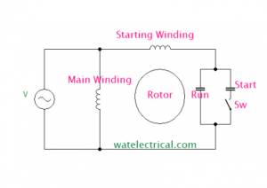
3) Capacitor Start Capacitor-Run Induction Motor
A capacitor is connected in series with the starting winding associated with a centrifugal switch and also a capacitor is connected in parallel to the starting capacitor. This capacitor is used to start the motor initially until it attains sufficient speed, after that the capacitor is disconnected by opening the switch. But the capacitor connected in parallel remains as it is to improve the running conditions. The capacitor start capacitor run IM is shown in the figure below.
Capacitor Start Capacitor Run Motor
The winding diagram of the capacitor start capacitor run IM is shown in the figure below.
Capacitor Start Capacitor Run
The phasor diagram corresponding to the capacitor start capacitor run motor is shown in the figure below.
From the phasor diagram, we can understand that the main field winding will be leading the voltage as it is capacitive nature due to the introduction of a capacitor. The starting torque would be high and with improved power factor and the running torque is also good. The running torque is good because though the starting capacitor is switched off, the running capacitor remains operating to maintain good torque.
Please refer to this link to know more about Single Phase Induction Motor MCQs
4) Permanent Capacitor
A capacitor is connected in series with the starting winding and is not associated with a centrifugal switch. This capacitor is used to start the motor initially and it also remains during the running conditions to improve the performance. The permanent capacitor IM is shown in the figure below.
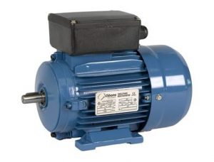
Permanent Capacitor IM
The winding diagram of the Permanent capacitor IM is shown in the figure below.
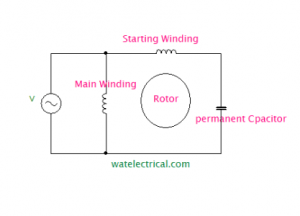
Permanent Capacitor Induction Motor Winding Diagram
The phasor diagram of Permanent capacitor IM is shown in the figure below.
Permanent Capacitor Phasor Diagram
From the phasor diagram, we can understand that, as the capacitor is used permanently in series with the starting winding. The starting and running torque corresponding to the anent capacitor motor is good.
5) Shaded Pole
The shaded pole IM consists of a squirrel cage rotor which is rotated under the salient pole magnetic field. ON end of the salient pole is attached by a copper coil which is also considered as a shaded ring which is short-circuited. Shaded pole type IM is shown in the figure below.
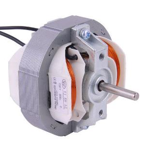
Shaded Pole Motor
The magnetic field induced in the main poles is induced into the shaded coil by means of an Induction Principle. The magnetic flux produced is an alternating field. The flux induced in the shaded coil opposes the flux of the main pole. During the positive cycle, the flux opposition is more towards the main field and vice-versa during the negative cycle. Thus, a rotating magnetic field is developed due to the field oppositions during the entire cycle. Therefore, a unique torque is developed which is able to rotate the rotor. This is the working of how it is a self-starting motor. The winding diagram of the shaded pole IM is shown in the figure below.
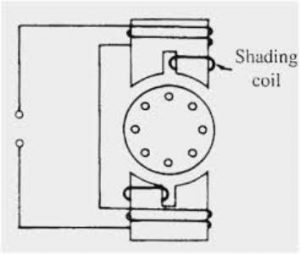
Shaded Pole Type Diagram
Applications of Different Types of Single-Phase Induction Motor
Split-Phase
- These are used for starting loads such as fans, blower-fans, mixer-grinders, and washing machines.
Capacitor Start
- These are used at heavy load applications such that where frequent starting is required.
- Used in air conditioners, compressors of Refrigerators, conveyor belts, and other machine applications.
Capacitor Start Capacitor Run
- These are used in heavy load applications and also where frequent starting and high inertia is required.
- Used in air conditioners, refrigerators, and pumps.
Permanent Capacitor
- This Motor has high efficiency and improved power factor. These are used in fans, blowers, air conditioners, and compressors in refrigerators.
Shaded Pole Type
- These are used for low starting applications such as in cooling fans, exhaust fans, blowers, fans of different types, relays, and in table fans.
- Cheap
- No need for an external source
- Self-starting
Disadvantages of Single-Phase Induction Motor
- Low starting torque
- More Looses
- Poor efficiency
- We cannot reverse the direction
- Low Power Factor.
Hence, we had an overview of a one-phase IM, it is a machine that works on the principle of electromagnetic induction. This RMF is developed by certain starting methods which enables the motor to self-start by itself. We had also studied what are the types of single-phase induction motor, Working, types of starting methods, advantages, disadvantages, and applications of different types of single-phase induction motor. Here is a question for the readers, what are the advantages of different types of one Phase IM?
Please refer to this link to know more about Electromagnetic Relay MCQs.
Picture Credit
Capacitor Start Capacitor Run Elmec Systems Kenya Ltd
Shaded Pole diagram with labels
Leave a Reply