In general, centrifugal switches are mainly used in single-phase and split-phase induction motors. The patent rights on this device were gained by Royal Lee during 1920. This stood as the foundation for the development of Lee Engineering Company. Before the development of centrifugal switches, the location of motors used to be inside the motor frame where it directed to the collection of a huge amount of grease, oil particles, dust which reduced the overall performance of the switch. Whereas with the invention of a centrifugal switch, this issue was resolved. And this article now explains on centrifugal switch working principle, its detailed functionality in the induction motor, and its implementation.
What is Centrifugal Switch?
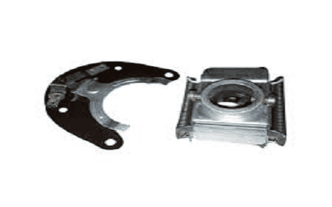
A centrifugal switch corresponds to the electrical switch which functions through the centrifugal force that was developed from the revolving shaft which is most commonly an electric motor.

Centrifugal Switch
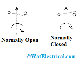
The switch is mainly manufactured either to activate or de-activate as the operation of the shaft’s rotational speed. These devices usually help in either switching ON or OFF the circuit activities based on the speed of the motor. The extensive use of these switches is to initiate winding cut-out for the single-phase induction motors and the centrifugal switch symbol is shown below.

Symbol of Centrifugal Switch
The type of switch which gets actuated using centrifugal force is termed a centrifugal switch. The device almost functions like a switch which is exemplified by an electric symbol. The electronic symbol represents that it is the picture representation of electronic circuits signifying the functionality of different electronic devices like transistors, wires, and many others.
Centrifugal Switch Working Principle
In general, these centrifugal switches are observed in single-phase and split-phase induction motors. The device is mainly for providing a regulated switching functionality which is necessary for the engine when the particular engine speed is created.
The operation of the device is mainly based on the principle of centrifugal force which is almost similar to the centrifugal clutch that is utilized in automobiles and the centrifugal switch is commonly termed as a clutch.
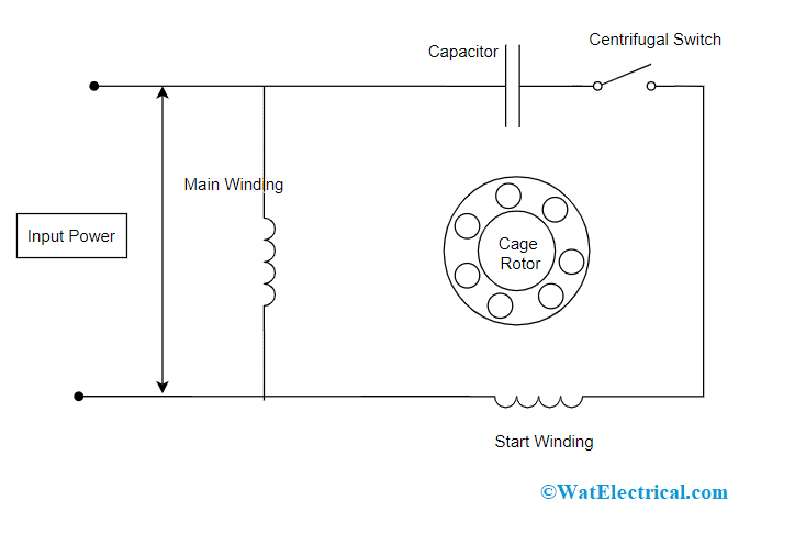
A single-phase AC engine consists of a centrifugal switch which is present inside the engine’s case that is connected to the shaft of the engine. When the engine moves into OFF and motionless condition, then the switch goes into the CLOSED state. Whereas when the engine is in switch ON condition, the switch then passes current to the capacitor and to the additional coil winding present in the engine which enhances the starting torque. As the revolutions of the engine enhance every minute, the switch will be OPENED because increased revolution reduces the dependability of boost.
Using a centrifugal switch, the issue that was in single-phase induction motors can be solved because single-phase motors do not have the ability of self-generating enough amount of torque required to initiate the switch from a dead stop position. A circuit turns ON the centrifugal switch by providing the required amount of boost to initiate the motor and again the switch switches OFF the boost circuit till the point motor gets to running speed and the motor functions smoothly.
This is the centrifugal switch working.
Functionality in Induction Motor
To know the function of the centrifugal switch in the induction motor, one has to know the principle behind induction motors. Induction engines are included with auxiliary and single stator windings. The stator winding is supplied with AC current, but it does not generate the required amount of rotating field to initiate the starting torque and because of this auxiliary winding is connected.

Switch in Induction Motor
The auxiliary winding produces a field that is external to the phase with the field produced by the stator winding. The output thus creates a starting torque and so the engine is started. Upon starting the engine, the rotor generates a pulsating field that does not consist of a stator field. When the speed of the engine reaches a certain extent of the synchronous speed, then the circuit which empowers the auxiliary winding to be disconnected. And here, centrifugal switches come into action which assists the circuit to get opened thus disconnecting the auxiliary winding.
This is the working of a centrifugal switch in an induction motor.
How to Test Centrifugal Switch
- Before using this device in any kind of application, it is recommended to test the device that ensures better performance. The switch is said to be in ideal condition when it met the below conditions:
- All across the device lifecycle, the device’s process has to consistent
- In order to make sure for minimal development cost and manufacturing, it has to be constructed with fewer components
- The device must have marginal components of friction
- The switch should not impose any kind of design changes either in the cut-out or cut-in proportions and it has to be readily adjustable
- The switch should be readily accessible to test, diagnose and replace where this creates easiness without disassembling the entire motor assemblage.
Applications
This section explains clearly the applications of centrifugal switch which are:
- The main implementation of this switch is in single-phase and split-phase induction motors. Here, the device is employed to disconnect the motor’s starting winding once it reaches to normal functional speed point of the motor. In this condition, the switch is included with weights that are mounted on the motor’s shaft and placed near the shaft using a spring force.
- Used in two-value motors which are also called capacitor-initiated capacitor run motors. A change in the switch utilized a changeover contact which makes sure that the auxiliary winding stays in the circuit using a functional capacitor.
- Implemented in cloth dryers where these supply power to the dryers along with the start switch. Throughout the period, the motor is functioning, the centrifugal switch provides power, whereas if there happens any blockage in the dryer, the switch will not supply power.
- Utilized in electric fans
- Used in aircraft also. Here, the switch is employed for regulating the ignition and initial circuits, the observed speed indication circuit, and the increased speed safety circuit. The switch is placed inside the revolving component.
- Also used in escalators, conveyor belts, and lifts
- Implemented in blowers, and fans
Please refer to this link to know more about Megger Test.
When compared with other types of switches that were used previously before the invention of centrifugal switches, these devices provide better contact reliability. As the switch location is not located inside the motor frame it is separated from dirt, grease, oil which generally comes in contact with the motor frame by spreading air currents. So, this article explained centrifugal switch working, testing, its functionality in induction motors and applications. Also, know why few types of split-phase induction motors do not consist of centrifugal switches?