These days human life is completely revolving around machines and technology. Advancement of technology has shown invention for multiple kinds of machines. And an electrical machine is the one which is crucial to transform one form of energy into another form. So, a machine will generate the output when there is a connection between the electric current and the magnetic field and this connection happened through coil windings. Motor windings hold utmost prominence in the operation of the motor and there also exist various types of windings used in motors. Thus, this article is all about the concept of motor winding theory, its design, calculation and the clear approach of knowing it.
What is Motor Winding?
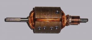
Definition: Windings in an electric motor are termed as coils where they are usually confined around a covered flexible iron magnetic core to structure magnetic poles though boosted with the current. These windings are utilized as components in various circuits and they stand as a support to provide a magnetic field for multiple generators, motors, and transformers. Windings are implemented in the circuits based on their dimensions and shape. Even factors like insulation strength, magnetic field capacity, Q-factor, inductance show effect on the shape of coil windings. Classification of coil windings is based on geometry and type of the wounded coil.

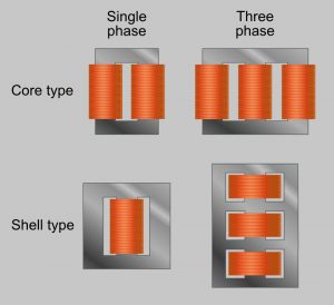
motor-winding-types
In the prominent pole structured machine, the magnetic field pole might be produced through a winding wound roughly under the pole direction and the winding can also be scattered internal to the slots of pole direction. A dappled pole motor consists of a winding that is positioned around the pole component which creates the phase of the magnetic field. Few kinds of motors consist of conductors having denser metal like metal sheets or else bars usually made of copper, or aluminum. In general, windings are power-driven components through electromagnetic induction.
Design
There are many approaches and techniques proposed to know about motor winding design. Here, this article shows symmetry conditions to design motor windings. These symmetry conditions are applicable for both the general and non-reduced systems where the mutual phase displacement is considered as
αph = 2∏/m = 2×1800/m
And in reduced systems, the mutual phase displacement is considered as
αph = ∏/m = 1800/m
When we consider an electrical machine, which has m phases, p pole pairs, N slots, and n layers, the winding design of this machine is known through knowing about number of wound coils in each phase, calculating which coils have varied phases ‘g’, and it is termed as
nwc = n (N-nes)/2m
g = nN/2mt for general and non-reduced systems and
g = N/2mt for reduced systems
Also, the design of the winding is based on the fill factor. Fill factor is defined as the relation between winding distance and the area of the electrical conductors. Increased fill factors are achieved when the windings are made of either flat or rectangular wires. And the fill factor is measured as
F = d2. (∏/4). n/b.h
Where ‘d’ corresponds to wire gauge along with the varnish isolation
‘n’ corresponds to the number of windings
‘b.h’ is the coil body cross-sectional area
Thick packing of wires decreases air space and it holds increased fill factor. This enhances the device efficiency and enhanced heat conductivity for winding.
Motor Winding Diagram
The below picture illustrates the diagram of the motor winding.

winding
Motor Winding Data Book
- Every motor winding machine has its own data book.
- For example, a washing machine has its own where the databook clearly specifies the dimensions of the wire, material used, no. of windings, insulation details and all other additional information regarding the wire.
Motor Winding Connection
The below process clearly describes how windings are connected to know about the motor winding calculation and how values are recorded. Through an ohmmeter, motor windings calculations are done. The connection can be done as follows:
- The positive end of the multimeter (red in color) is connected to the positive end of motor windings.
- In the same way, the negative end of the terminal (black in color) is connected to the windings negative end
- The readings for the motor winding machine are recorded and those readings are presented on the multimeter screen and corresponding resistance is calculated in ohms.
- Now, with the assistance of an ohmmeter, isolate the power supply and the motor. Place the meter on ohms and usually, the range will be in the order of 2 -3 ohms. When the readings are zero, there happens a short circuit. And when there exists an open circuit, the range will be of more than 2K ohms or infinite.
Now, we shall know more about how the motor winding wire is made and what are they made of? Basically, the raw material which is used for both the circular and rectangular wire is either aluminum or copper. Mostly motor winding wire is made of copper. Rectangular shaped wires are made of extrusion procedure where a wire rod is hard-pressed via a die to gain its final shape. And for round copper wires, they gain their shape after several stages of cold drawing. In many of the electrical machines such as inductors, generator and transformers copper enameled windings are used. These wires perfectly satisfy the properties of resistivity, inductance, temperature conditions and many other factors.
Machines
Electric motor winding machines are in more prominence these days and they became a part of our day-to-day life. There are multiple classifications of these winding machines like automatic, semi-automatic, manual, computerized and non-computerized. Windings are necessary to make all these machines to run and generate the output. Few of the example of motor winding machines are as follows:
- Refrigerator
- Washing Machine
- Generator
- Paper machines
- Foil machines
- Film and spool winding machines
FAQs
1). Why motor windings are insulated?
The windings ha to be given with proper insulation either with a varnish or resin. Perfect insulation for windings shields them from any kind of adulteration, electrical shortages and make them stronger mechanically.
2). What are the motor winding types?
The fundamental classification of motor windings are open, closed, field and armature windings.
3). Coil and Windings; what are the differences?
A coil is one turn of the whole winding wire. Whereas winding corresponds to an array of coils.
4). Why windings are failed?
The foremost factor of motor windings failure is low resistance. Low resistance happens when there is degradation in the winding’s insulation. Degradation happens because of corrosion, overheat and other physical damages.
5). What is varnishing in a motor winding?
To increase the efficiency of the motor, varnishing is done to insulate the windings from any kind of contaminants and so they will so tight and stiff.
Thus, this is all about an overview of the motor winding concept, These windings are more crucial in every electric machine, so they can ha to be properly selected and implemented. Multiple factors are taken into consideration to know the best quality so that factors like resistivity, insulation, and conductance enhance the quality, life-period, and effectiveness of the wire. Get to know more about machine windings and how they can be manufactured?