In many of the practical applications, the output of a single-stage amplifier is not sufficient to provide the required bandwidth or gain. So, the enhance either power or voltage gain, the multistage amplifier is required. These kinds of amplifier circuits hold the ability to offer augmented specifications and enhance the circuit performance and so preferred as fundamental building circuits for the development of complicated amplifier networks. This article clearly explains the concept of multistage amplifiers, their design, configuration types, and applications.
What is the Multistage Amplifier?
When the output of the previous stage is connected as an input to the following stage through a coupling device, it is termed as a multistage amplifier. For the purpose of coupling, either a transformer or capacitor is used. So, the procedure of connecting two amplifier levels with a cascading tool is also specified as Cascading. The below picture clearly depicts how the amplifiers are connected.

Multistage Amplifier
And from the above diagram, the gain of the circuit is the multiplication of all the individual stages where it is given by:
VM = VM1 × VM2
Where ‘VM’ is the overall voltage gain of the circuit
‘VM1’ is the voltage gain of the first amplifier and ‘VM2’ is the voltage gain of the second amplifier.
For instance, when a circuit has ‘n’ stages, then the overall voltage gain is the product of all the individual stages present in the circuit.
VM = VM1 × VM2……………. VMn
Design
A multistage amplifier design can be done in multiple ways and the cascading provides increased input and minimal output resistance values and improved gains. Let us consider common emitter (CE) and common collector (CC) cascading design.
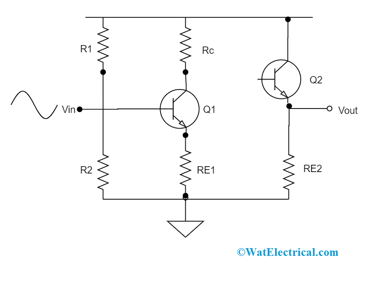
CE-CC Connection
Here, the cascading of the CE amplifier with that of the CC amplifier will show enhanced voltage gain. The CE amplifier input resistance is comparatively more and the CE output resistance is comparatively minimal. The Q2 amplifier provides no enhancement in the voltage gain, whereas it offers a minimal resistance path and this shows that gain does not depend on the output resistance. While Q1 amplifier contributes that the input resistance does not depend on the input-source resistance. Many CE stages are cascaded might be connected with the emitter subsequent stages that are placed between them to minimize the attenuation levels because of the inter-stage of loading.
For every stage, DC biasing circumstances and the resistance values can be known in the way similar to that of single-stage amplifiers.
Frequency Response
Frequency response is the graph where the relation between frequency and the voltage gain can be known. As RC coupled amplifier is a multistage amplifier, let us consider the frequency response of this multistage amplifier.
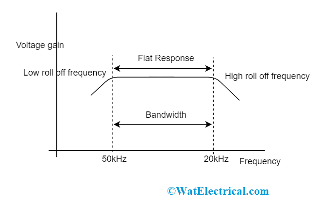
Frequency Response
In the above graphical representation, it can be known that frequency value decreases in the frequency range of >20kHz and <50kHz. Whereas in the ranges of 20kLz – 50kHz, the frequency value stays as constant and
Xc = 1/(2∏fc)
This means that capacitive reactance has an inverse relation with that of frequency values.
Multistage Amplifier Types
When the amplifiers are connected using a coupling device, it is termed as interstage coupling. The type of coupling decides the classification of the multistage amplifier and those are as follows:
- Direct coupling
- Transformer coupling and
- Capacitor coupling
Direct Coupling (DC)
In a few of the amplifiers, both AC and DC are connected between the amplifier stages. Whereas in the direct coupling, the collector stage output has a direct connection (or through resistance) with the base stage and this does not show any blockage to DC. The direct coupling type permits the amplification of extremely minimal frequency values along with 0Hz. Mostly, wideband amplifiers employ this type so as to remove the usage of capacitors, because capacitors may cause increased frequency instability conditions. With this, there might have changes in the output gain at few frequency levels.
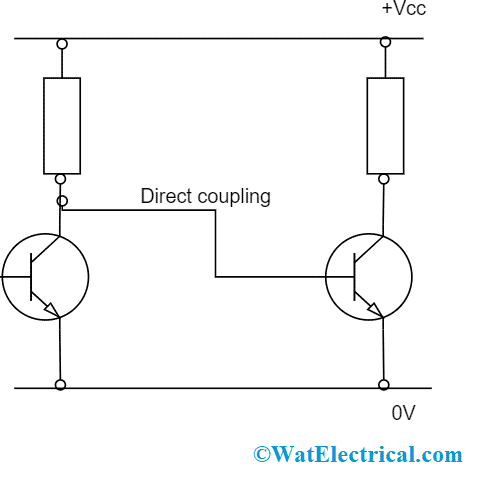
Direct Coupled Multistage Amplifier
Multistage amplifiers that are coupled through this approach need to have good stability mainly in correspondence with temperature changes. Even a minimal variation in the biasing conditions at the transistor base will deliver extremely high changes at the collector. This will generate an error (error means the variation in the correct voltage and the estimated collector voltage level).
Transformer Coupling
In this type of coupling, the current flow at the collector of one stage will stream via the primary winding of the transformer. This stimulates signal voltage to the secondary winding which is connected at the input of the following stage. This signal is connected to the DC biasing at the base end of the following stage.
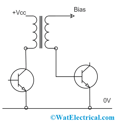
Transformer Coupled Multistage Amplifier
Here, DC is obstructed and the AC signals are cascaded, and the ratio of transformer turns might be even employed to offer impedance matching between the amplifier stages. This coupling type is most appropriate for the RF amplifiers as the reason that the size of the transformer can be maintained so small.
Capacitor Coupling
This type of coupling method offers electrical separation (which means blockage of DC) between the cascaded stages and permits the AC signals. This scenario permits for a various base and the collector voltages on the cascaded stages and minimizes any kind of DC stability complications. Through this approach, the capacitor reactance should be so minimal at the low signal frequency range where this not extensively minimize signal in between the stages.
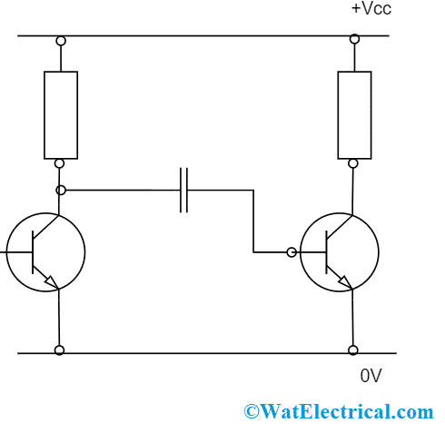
Capacitor Coupling
Applications
The multistage amplifier applications can be found in various industries in various scenarios and those are:
- Employed in the conditions when perfect impedance matching is required
- Used in the applications when correct frequency response is necessary
- These amplifiers are also used for DC isolation purposes
- Applications those need enhanced gain, and good flexibility
- Enhanced bandwidth
- Multistage amplifiers designed with MOSFET devices are also employed in many applications
- Audio transformers
- Microphones
- Multistage amplifier cascading is used for high-voltage and high-speed applications.
Know more about Capacitive Reactance MCQs.
So, this is all about the multistage amplifier analysis. With this multi-port network, one can find many advantages and applications. The drawbacks of minimal bandwidth, imperfect impedance matching, and required gain levels from single-stage amplifiers can be easily overcome through the design of multistage amplifiers. Know more about the concepts related to this such as how an RC (resistance-capacitance) coupled multistage amplifier operates?