As the prominence of audio, video and other broadcasting technologies are enhancing day-by-day. There have to be certain amplification ranges to increase the quality and effectivity of the broadcasting signals. In the scope of this, the first amplification device that came into existence was a triode vacuum tube in the year 1906. There come many devices used for this cause and those are transistors, multistage amplifiers, and RC coupled amplifiers. As because of the few shortcomings in the RC coupled amplifier, the transformer-coupled amplifier got introduced. Let’s move ahead with the discussion of how the transformer-coupled amplifier is working, its benefits, and others.
What is Transformer Coupled Amplifier?
Definition: These amplifiers come under the classification of multistage amplifiers. Through the principle of coupling, one stage amplifier is connected to the next stage amplifier. This coupling scenario allows gaining impedance stability through the connection of the transformer. If any of the stages have high/low impedance values, it can be balanced when connected with the other stage. Because of this, power and voltage values are enhanced. In general, these are utilized for minimal load purposes and where power amplification is necessary.
Transformer Coupled Amplifier Circuit Diagram
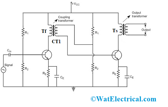
The amplifier where the preceding stage ones are connected to the subsequent stage amplifier through a coupling transformer is termed as a Transformer Coupled Amplifier. The output of the first phase (TF) is connected to the input of the second phase (TS) through a coupling transformer (CT1). The load through the collector is substituted by the transformer’s primary winding. Whereas the transformer’s secondary winding is positioned in between the base of the second phase and the potential divider and this connection is fed as input to the second phase. As a replacement for coupling capacitor such as in RC coupled amplifier, a transformer is utilized for the purpose of coupling in the transformer-coupled amplifier.
The stabilization and the biasing networks are formed with the connections made through Re and the potential divider circuit (R1 and R2). The signal receives the minimal reactance path from the emitter by-pass capacitor which is CE. The connection for the transistor base and the AC signal is coupled through the input capacitor which is located at the first amplifier. So, the coupling capacitor provides a connection for both the amplifiers which also eliminates the DC intrusion in between the amplifier stages and handles the operating point shifting position.

Transformer Coupled Amplifier Circuit
Transformer coupled amplifier working can be explained as follows:
When the base section of the initial transistor receives alternating current signal then the transistor amplifies the signal and the amplified signal is observed at the transistors’ collector section where it has a connection with the primary transformer. The coupling operation is performed by the transformer and even it holds the principle of varying impedance where it corresponds that minimal resistance value of the load might get reflected as the maximum resistance to the preceding stage. As because of this scenario, the voltage which appears at the primary winding is transferred to the secondary winding and it is based on the number of turns present in the transformer.
The principle of coupling shows maximum impedance matching between the two stages of the amplifier. So, the foremost application of the transformer-coupled amplifier is for power amplification. This is the basic working principle of a transformer-coupled amplifier circuit.
Frequency Response of Transformer Coupled Amplifier
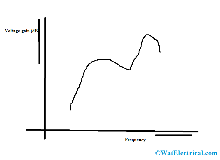
As frequency response corresponds to the measure of systems output respective to the input parameter and this is used to know the efficiency of the system. Here, in this circuit, the amplifier gain is always constant for a minimal range of frequency levels. The current across the collector multiplied by the primary winding reactance is similar to the output voltage value. At minimal frequency levels, the primary winding reactance will start to decline thus shows in minimal gain, whereas at maximum frequencies, the capacitance value between the primary and secondary windings performs as the bypass condenser to decrease the gain so that output voltage is also reduced. So, there will be the addition of few interference signals and the amplification levels are not similar to that of the input signal and are termed as Frequency distortion in the transformer amplified circuit.
The below diagram is the frequency response of the circuit.

Frequency Response
Advantages/Disadvantages
The advantages and disadvantages of a transformer-coupled amplifier are:
Advantages
- There will be no loss in the power values of the signals either in the base or collector resistors
- Through transformer coupling, maximum impedance matching can be obtained.
- High values of impedance matching provide maximum gain. A perfect constructed single amplifier coupling can offer gain at both the phases of RC coupling
Disadvantages
- Shows minimal frequency response values
- Complicated to construct as the size is heavy also these are costly devices
- There will be maximum frequency distortion which means that minimal frequency value signals are amplified less than compared to that of maximum frequency value signals
- There will be an addition of some interference in the output signals.
Applications
The applications of a transformer-coupled amplifier are:
- The foremost application of these devices are for impedance matching purposes
- In these devices, the final amplifier is the power stage amplifier and so necessary to transfer maximum power levels to the output device
Example: A Loudspeaker
- As the output impedance is only fewer ohms and the output impedance values of the transistor are high. So, these amplifiers are utilized for high impedance applications
- Mostly, impedance matching is easily achieved through this circuit connection.
- As the primary winding load is equivalent to the transistors’ output impedance and this shows higher power values to be transferred to the transformer’s primary winding.
FAQs
1). Can the transformer work as an amplifier?
A transformer cannot be operated as an amplifier as the output and input power levels are similar and there will be no other source other than that of the signal.
2). What is the use of coupling in the amplifier?
Coupling is necessary to connect two amplifiers through a capacitor.
3). What is a coupling transformer?
A transformer is said to be coupling when the output of one amplifier is connected as an input to the other.
4). What is the purpose of RC or transformer coupling?
The functionality of the transformer coupling is to allow the alternating current signals and to block the direct current biasing voltages.
Know more about Phase Shifting Transformer.
This is the comprehensive concept of the Transformer coupled amplifier and because it eliminates the drawbacks of the RC coupled amplifier, this circuit has more applications. The amplification of these devices can be enhanced through multiple coupling methods such as coupling capacitor and transformer. And the unique feature that allowed this device to gain more significance is its higher efficiency at the output. So, know more about what are the other features in the transformer-coupled amplifier?