For the functioning of many electronic circuits, filters hold the most importance. So, people in the domain of electric and electronics, show interest in the development of filters. In general, a filter is termed as the electric network which modifies either the amplitude of phases of the signal corresponding to the frequency. And then the active filter is the analog circuit which is designed using active components usually amplifier. And these active filters are classified as HPF, LPP, BPF, and BSF filters. So, this article is all about the discussion of Active Low Pass Filter, its calculator, types, and applications.
What is a Low Pass Filter?
The functionality and frequency response of the active low pass filter is almost similar to that of a passive filter. So, when a passive filter is connected either to the inverting or non-inverting operational amplifier is termed as an active low pass filter. The output signal’s amplitude is minimal than that of the input signal’s amplitude in a passive filter, and to overcome this downside, an active low pass filter is developed. In the first order, The below circuit explains how LPF is designed.
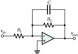
Active Low Pass Filter
For the first order low pass filter, the circuit is designed with a passive RC filter thus offering a minimal frequency path for the input of the non-inverting op-amp. This configuration of active low pass filter offers enhanced stability and increased input impedance. So, a DC gain of unity can be attained whereas for passive filter the gain will be less than one.
DC = 1 + (R2/R1)
In relation to frequency, the gain of the LPF is represented as
Voltage gain = (Voltage output/voltage input) = AF/(sqrt(1+(f/fc)2))
Where AF is the gain of the bandpass filter that is 1 + (R2/R1)
‘f’ is the input signal frequency and
‘fc’ is the cut-off frequency
Whereas, the magnitude of voltage gain is represented as
Av in dB = 20log10(voltage output/voltage input)
And the frequency response curve is:
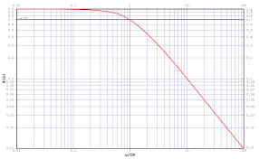
First Order LPF Frequency Response
fc = 1/(2ΠCR2) calculated in Hertz
Second-Order Low Pass Filter
Using the passive filter, a first-order LPF can be turned into a second-order low pass filter along with the addition of an RC network across the input way. Almost, the frequency response values are similar for both the filters, apart from the stopband roll-off will be double than that of first-order LPF.
The design of the second-order filter is shown as:
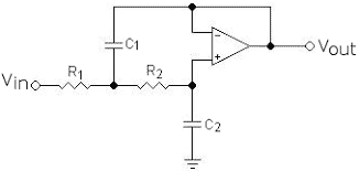
Second Order Low Pass Filter
The design has two RC networks such as R1C1 and R2C2 so that it attains frequency response features. Based on the non-inverting operational amplifier design, the second-order LPF is designed and so the gain is more than unity. As because the operational amplifier is used and it has greater input impedance value, the circuit is simply connected to other filter circuits so that a complicated filter can also be designed.
For this filter, the values of frequency response and gain are given by:
Gain = 1 + (RA/RB)
When the resistor and capacitor values are not similar, then the frequency response is
fc = 1/(2∏sqrt(R1R2C1C2))
Whereas when the resistor and capacitor values are similar then,
fc = 1/(2∏RC)
In these second-order low pass filters, quality factor and dumping factors are autonomously known by the amplifier gain, so when the ‘Q’ factor reduces then the damping factor enhances.
Low Pass Filter using Op-Amp
Low pass filters have greater efficiency when operational amplifiers are used. The feedback loop of the operational amplifier is simply unified with the fundamental elements, and this gives increased performance low pass filters.
Using a feedback resistor and the capacitor, first-order low pass filter using op-amp can be designed. Here, when the feedback level is increased, then the frequency increases but the capacitor value gets reduced and the circuit is as below:
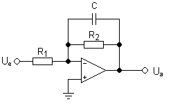
First Order LPF Using Op-Amp
Here, Xc = 1/(∏fc)
Where ‘Xc’ corresponds to capacitive reactance calculated in ohms
‘f’ = frequency calculated in Hertz
‘C’ = capacitance calculated in Farads
Second-Order Low Pass Filter using Op-Amp
Even though there are many kinds of filters having various gain levels and various patterns are designed through the assistance of operational amplifiers and other basic components. This second-order LPF offers simple construction and direct calculations.
With this design, the circuit offers a gain of one and a Butterworth frequency response. The circuit design is shown below:
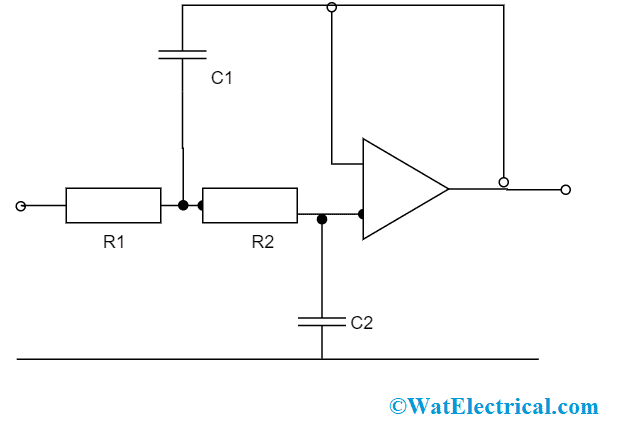
Second Order LPF Using Op-Amp
For instance when R1 = R2 and C1 = 2C2, then the frequency response is
f = sqrt(2)/(4∏RC2)
So at the time of selecting the component values, make sure that the resistor values to be in the range of 10 kΩ and 100 kΩ. This is because the value of output impedance increases with that of enhancing frequency and values exterior to this region and this might show an impact on the entire performance of the operational amplifier.
LPF Applications
In the electronics domain, there are extensive low pass filter applications and those are given by:
- The low pass filters are implemented as hiss filters in the audio speakers. When these are used, the high-frequency hiss generated in the system is lessened
- Also used as input circuits for sub-woofer systems.
- Implemented in audio amplifiers and equalizers.
- In ADC conversion, these LPF filers are used as anti-aliasing to manage signals whereas, in the digital filters, the low pass filters are utilized for the purposes of signal smoothening and picture blurring.
- Implemented in radio transmitters for the obstruction of harmonical emissions.
- In the acoustic domain, low pass filters are used for filtering a high range of frequency signals thus reducing the high echo produced by high-frequency range signals.
FAQs
1). Where low pass filters are used?
Low pass filters are mostly used in speakers, equalizers to lessen the high range of noises.
2). Why are active filters better than passive?
The quality factor is more in the active filters than that of passive filters and so active filters are better.
3). Why do we use filters?
Filters are the electronic circuits that hold the capability of either attenuating or amplifying a desired range of signals and also to reduce noise.
4). What are the demerits of passive filters?
Passive filters have a more harmonic current flow, generate only minimal response and also these are minimally sensible to temperature variations.
5). What is the need for a filter?
A filter is the circuit used for the functioning of frequency selection and to attenuate an undesired range of signals.
So, this article provides detailed information related to active low pass filter, how first order and second-order low pass filters are designed, their derivations, low pass filters using operational amplifiers and their applications. Making use of a low pass filter calculator, and knowing the values of either resistance or capacitance values, the frequency response values are easily calculated. Also, know how the frequency response curves of low pass filters are altered based on the voltage values.