The current transformer (CT), also known as an instrumental transformer, is used to either reduce or propel the primary current across the secondary winding. The current produced across the secondary terminal is directly proportional to the primary winding. In high power circuits, the voltage across the primary side is scaled down to a minimum value, which helps to measure the actual AC transmission current through standard ammeter safely. In this article, an in-depth theory about the current transformer, its working principle simple diagram, the various types, errors, advantages, and its typical applications can be perceived throughout the article. Similar to voltage and power transformer, this transformer comprises a primary and secondary winding with a minimum or only a few turns at the primary winding. The secondary winding consists of a higher number of turns to withstand the maximum voltage and current. With the above brief about the current transformer, the reader may get a question to know the standard definition of “What is the current transformer?”
What is the Current Transformer?
Definition: In technical words, the current transformer is defined as a measurement unit that converts the high-level current to a level that is suitable to operate in normal conditions. It may vary based on the type of applications, the requirement based on the community such as industrial and domestic purposes, and so on. The proper functionality, equipment control, and operation data system can be easily ensured by leveraging the current transformer in series with the primary circuit. This transformer is majorly divided into two types, namely measuring CTs (converts current to a quantifiable range of meters and instruments) and protection CTs (integrated with protective relays for proper operation under transient conditions).
The current transformer diagram consists of a primary and secondary coil with one or more turns in the cross-sectional area. In some cases, this transformer is connected in series with the main circuit, and the other encompasses a bar casing, which acts as primary and coil as a secondary circuit. The number of turns with a fine-tuned cross-sectional area is designed as a secondary of the current transformer. The maximum current rating of the circuit is 5A.
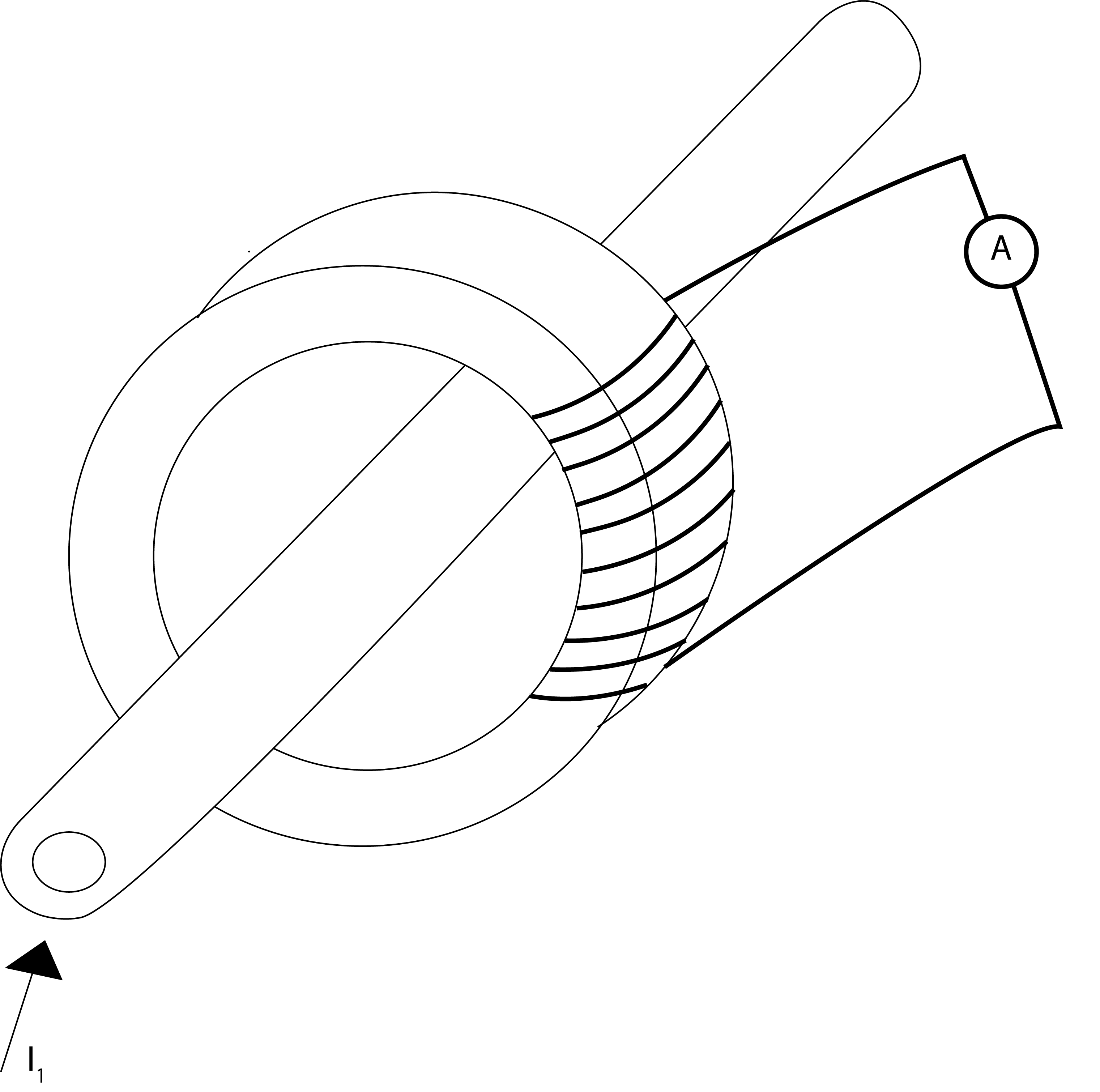
current-transformer
Working Principle/Working of Current Transformer
Generally, this is used for either stepping-up or stepping-down the input voltage and current of the primary circuit. But in real-time applications, this transformer is used in high voltage applications; hence it brings-down the current to the considerable value.
The standard formula for calculating the number of turns is given by,
I1 /I2 = N1/N2—— (1)
Where,
I1 = The current across the primary winding
I2 = The current across the secondary winding
N2 = Secondary turns count
N1 = Primary turns count
P = VI——(2)
Where P = Power
V = Voltage
I = Current
As per the power calculation equation (2), the voltage and current are directly proportional to each other. It is required to increase the number of turns across the secondary winding should be kept high, which in turn reduces the voltage, current, and enables easy current measurement.
Construction of Current Transformer
As discussed in the above sections, the current transformer is divided into three types namely,
- Bar type transformer
- Wound type transformer
- Toroidal type transformer
Bar Type Transformer
The bus bar or actual live wire is considered as the primary winding of the current transformer. It typically comprises of only one turn at the primary side and is end-to-end insulated to withstand high operating conditions. The outer core acts as a secondary winding. In comparison to an ordinary transformer, there is a high number of stampings that covers the large cross-sectional area of the core and laminations. This process enables low reluctance, and small magnetizing current is induced at the corners of the secondary side
Distance between individual windings is kept low to minimize the reluctance effect and large external diameter to eradicate the corona factor. Moreover, the complete circuit is designed to avoid the short circuit developed inside the coil.
Wound Type Transformer
In this type, one full turn of the core is wounded with the primary circuit. Bakelite former of the low voltage type current transformer is covered with the secondary winding. With suitable insulation ratio, the primary coil is wound above the secondary winding, and the insulation between these windings is designed on the basis of application. Another procedure includes the separate tapping of primary material with an insulated core.
Generally, oriented electrical steel or nickel-iron alloy is used as a core material. The end collars and circumferential wraps of pressboards are considered as an insulating material prior to secondary winding installations. This process enables additional winding insulation and protection from uncontrolled actions such as sharp corner damages.
Toroidal Type Transformer
There is no requirement of primary winding in this type of transformer. The current-carrying line that is directed inside the network is threaded through the window of the toroidal coil. Hence, it is also named as “window transformer.” Some of these types also comprise of a split core that can be opened, closed, and installed without removing connections from the circuit.
Types of Current Transformers
With respect to the applications, this transformer is broadly categorized into two types, indoor and outdoor current transformer.
In an indoor type, the absence of primary conductor results in the deployment of primary insulation over the busbar or a conductor. Based on applications, it is further divided into cast resin and tape insulated materials. Similarly, the outdoor type is designed and manufactured concerning external features and functional characteristics.
Notably, to withstand the fragile, wear and tear conditions. Cooling and insulation are achieved by employing transformer oil or other suitable liquids. A unique liquid –immersed CT is developed, which operates in a sealed environment and minimal connectivity with the external environment.
The outdoor oil-filled CT is further categorized as follows,
- Live tank-type current transformer
- Dead tank-type current transformer
A live tank type current transformer is mostly observed in distribution systems. The transformer core is immersed inside the oil tank to extinguish the generated heat or spark. The bushings act as an insulator to separate the primary terminal. The bushings are more prone to damages as it is flexible and transit to the center of gravity from the more towering height.
In dead tank type current transformer, the core surrounded with oil is placed at the earth potential. In this type, the center of gravity is low or negligible and avoids the damage due to transit. The bushings are compact and easily mounted near the outdoor steel structure of circuit breakers.
- As per theoretical calculations, the construction of this is majorly dependant on four factors namely,
- Primary and secondary turn ratio (For example, 1200/1).
- Load capacity: The normal VA load that the transformer can efficiently carry without any burden.
- Transformer accuracy factors in both transient and steady conditions.
- The physical configuration parameters such as the number of turns in primary and secondary windings, shape, size, and so on.
Errors in Current Transformer
In real-time applications, the transformer will not work as per the theoretical expectations. The reason is due to the external climatic effect, durability of materials, and its connectivity with other networks. In general, the error in the actual current transformer is calculated on the basis of the phasor diagram.
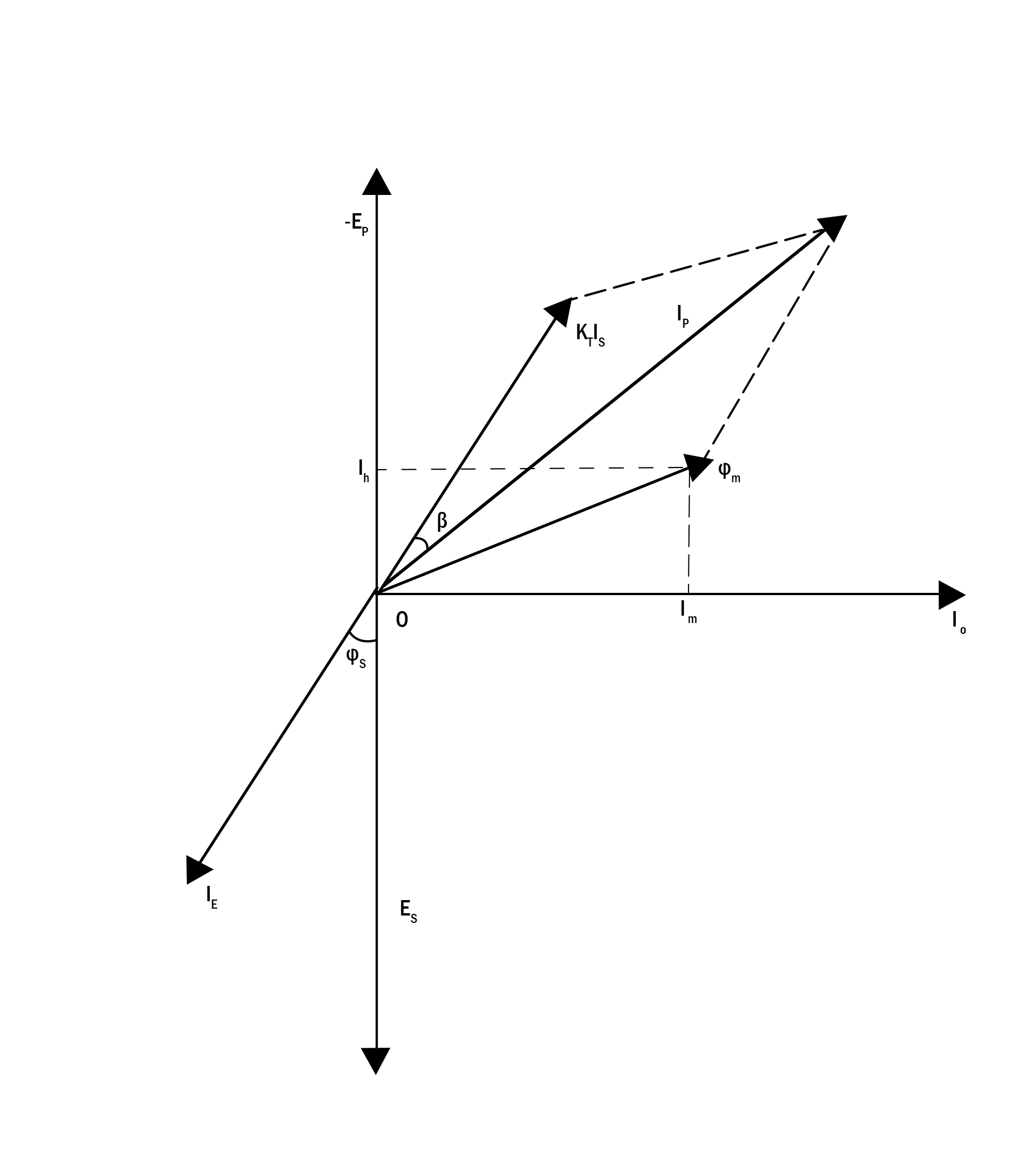
current-transformer-phasor-diagram
Let,
IS = Secondary current
ES = Induced EMF across the secondary terminal
IP = Current across the primary winding
EP = Induced EMF across the primary terminal
KT = Number of turns ratio (i.e. secondary turns versus primary turns)
Io = Minimum excitation current
Im = Magnetizing component with respect to I_o
Iw = Core loss with respect to I_o
ϕm = Main flux
During analysis, the main flux is considered as a reference, the induced EMF factors ES and EP lag by 90 degrees, and magnitude is proportional to the primary and secondary turn ratio. Io is calculated using the components Im and Iw. ϕs is the angular difference between the secondary current and secondary induced EMF. The negative factor of IS and its multiplication with turns ratio KT produces the total current transferred across the primary side.
The vector sum of KT IS and Io is the overall current across the primary winding. The inference from the above phasor diagram shows that IP is not the actual value as per the calculation. The difference is contributed to the core excitation current and results in the ratio error in the current
transformer.
Current error (%) = (|IP |-|KT.IS |)/IP *100
The phase angle β is the phasor difference between the reversed secondary current vector and the primary current vector. In ideal conditions, the value is zero, but there is always a supply component for excitation current that leads to this type of error. Furthermore, a part of the current consumed for core excitation will also lead the error generation.
Reducing the Errors in the Current Transformer
In any electrical, electronic, and mechanical system, maximum efficiency can be achieved with minimal errors. Several precautionary measures have been noted to reduce the errors, and they are as follows,
- Considering a high permeability core and low hysteresis loss magnetic materials during construction.
- The difference between the rated burden and actual burden should be as low as possible or zero.
- The flux path length and connectivity joints should be as minimum as possible.
- Reducing the secondary internal impedance.
Advantages
The advantages are;
- The larger current values can be easily measured.
- Its capability to isolate the high voltage and current to low values ensure safe operations and handling
the equipment in a safe manner. - It can be used as a controlling device to operate protecting devices such as relays and pilot lights.
- Numerous instruments can be feeding on a single transformer.
Applications of Current Transformer
The disadvantages are;
- It is extensively used to convert and measure the current flowing through the power grid.
- The high accuracy has enabled users to connect at metering points.
- It is used to calculate the harmonics and monitor power quality through the frequency response cycle.
- It is suitable for converter applications in substations, HVDC projects, in AC, and DC filters.
- As a protection device in high voltage mains and substations.
- It is used as an integrated protective module in capacitive banks.
- In revenue metering applications.
know more about Instrument Transformer MCQs.
Please refer to this link to know more about Distance Relay, Potential Transformer , Cooling Tower.
In general, the current transformer empowers users to detect the high-value current across the circuit. Though it is beneficial in real-time applications, drawing precise readings without harmonics and current error is a crucial task. Moreover, with increased demand, the accurate and development of automatic digital current transformers reduces the power loss during transmission, and also transmit or calculate the load demand as per the user requirements at that instant of time. Here is a question for you, what are the main features of the current transformer?