Ferranti Effect is one of the undesirable phenomena that happens in power systems. Fundamentally it explains the rise in receiving end voltage as compared to sending end voltage due to line capacitance and inductance for a long transmission line i.e. the transmission line with length greater than 160 km. Conceptualized by Sir S. Z. Ferranti in the year 1887, this effect explained the impact of line capacitance on receiving end voltage under no load or light load conditions. This article discusses an overview of the Ferranti effect.
What is the Ferranti Effect?
Definition: It can be defined as the rise in receiving end voltage as compared to sending end voltage for a long transmission line under no load or light load conditions. This phenomenon can be explained based on the phasor diagram, mathematical expressions for sending and receiving end voltage and based on reactive power flow in the transmission line. This is explained individually as follows:
Ferranti Effect Circuit Diagram
Consider the following equivalent circuit of a transmission line and its phasor diagram. The below figure shows the equivalent circuit of a long transmission line where R, L, C are line resistance, inductance and capacitive respectively. In the equivalent circuit, they are approximated as lumped elements instead of distributed. Now it is to be noted that line resistance, inductance, and capacitance all are directly proportional to the length of the line. So for a long transmission line, all will have a dominant effect. Let IC be the charging current i.e. the current flowing through the capacitor, IS be the sending end current and IR is the receiving end current.
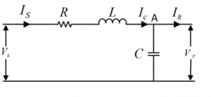
equivalent-circuit-of-long-transmission-line
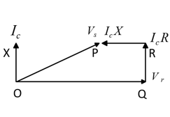
The following figure shows the phasor diagram for the equivalent circuit. Since we have assumed the line to be operating at no load, therefore IR =0 and IS=IC. And charging current IC will have drop across R and L given by ICR and ICX which are represented by QR and PR in the phasor diagram. Since charging current IC is leading with VR it is represented with OX in the phasor diagram. Writing simple KVL equation for the above figure we can see that
VS =IC X + IC R + VR .
When represented in the phasor diagram, as shown due to the leading nature of charging current, the vectors QR and PR when added OQ, i.e. VR, the value of VR becomes greater than VS. Hence under no-load condition, the line capacitance dominates the line inductance, and the drop across line inductance due to charging current which is leading in nature makes receiving end voltage greater than sending end voltage. Let’s analyze this phenomenon in terms of mathematical expressions for receiving and sending end voltage.
phasor-diagram
Ferranti Effect Equations
The sending end voltage for a long transmission line can be expressed as
VS = (VR + IR ZC )/2 * eαx e jβx + (VR + IR ZC )/2 * e-αx e -jβx ——–(1)
Where VS is the sending end voltage, VR is the receiving end voltage, IR is the receiving end current. ZC is the surge impedance, α is the attenuation constant, β is the phase constant and x is the distance from receiving end side. It is be noted that the first half of the right side of equation (1) is also known as an incident voltage which keeps increasing with length of line and the second half is known as reflected voltage which decreases with the length of the line.
For x=l (long transmission line) and IR =0 (no-load condition) equation (1) becomes
VS = VR /2 *eαl eβl + VR /2 *e-αl e-βl ——–(2)
With l=0 the above equation becomes
VS =VR /2+VR /2——–(3)
Equation (2) implies that with an increase in length l the incident voltage increases exponentially in magnitude (VR/2*eαl) and turns through a positive angle βl. While the reflected voltage wave decreases in magnitude exponentially (VR/2*e-αl) and turns through a negative angle βl. From a basic analysis of equation (2), it is apparent that VR becomes greater than VS. Now let’s analyze the Ferranti effect based on reactive power flow.
Reactive Power Flow
From the fundamentals, we know that, if at a particular node the reactive power generated is more than reactive power absorbed, then the voltage at that particular node becomes higher than the normal value. From figure Fig 1(a) it can be observed that at node A, due to dominant line capacitance (since we are considering long transmission line) the net reactive power generated is more than reactive power absorbed due to line inductance. This clearly indicates that the voltage at node A, VR (due to no-load condition) becomes greater than VS, which clearly explains the Ferranti effect. The line inductance acts as a sink whereas the line capacitance acts as a source for reactive power. Further adding to it, the loading at this condition i.e. during Ferranti effect the loading must be less than surge impedance loading (SIL).
Ferranti Effect Reduction
Since it is apparent that the Ferranti effect is mostly due to line capacitance, or in other words active power generation, to overcome this effect we need a reactor to compensate the line capacitance. This is known as the shunt reactor which is installed at receiving end side to balance the reactive power. It absorbs the reactive power and compensates for the line capacitance effect. One more method to overcome is obviously to avoid no-load condition or adding load at the receiving side. Most of the loads are inductive in nature, which will definitely meet the criteria.
Advantages
Ferranti effect doesn’t have any advantages except for the fact that it helps in designing the transmission system and protection levels. Based on the Ferranti effect the amount of shunt reactor compensation is also done. Since the Ferranti effect is due to capacitive and inductive reactance, obviously for HVDC systems Ferranti effect would be absent. Hence it helps in the calculation of HVDC systems also. Additionally, engineers can study electronic switching based on Ferranti effects.
Disadvantages
Like skin effect and proximity effect, Ferranti effects also have undesirable effects on the power system. Since the receiving end voltage becomes greater than sending end voltage, the loads at receiving end side which is designed based on the nominal value of voltage i.e. sending end voltage could be damaged. Damage of sensitive loads could cause further loss to utility. Similarly, the rise in voltage would cause unnecessary losses that affect the performance of the transmission line. From the protection point of view, the circuit breakers which are designed at sending end voltage level, when sensing the rise in voltage will trip the transmission line which further needs maintenance. The compensation of reactive power can be further done using FACTS devices.
Know more about Vacuum Circuit Breaker MCQs.
Thus, this is all about what is the Ferranti effect, circuit diagram, equations, reactive power flow, reduction, advantages & disadvantages. Here is a question for you, what are the applications of the Ferranti effect?