 If any unexpected fluctuation in the power supply may cause many problems in the industries, homes, offices. Voltage fluctuations in the electric power supply have a very poor effect on connected load. These fluctuations of over voltage and under voltage protection system are produced by many reasons which are like voltage surges, limiting, overload and etc. General applications of these systems are used in agriculture motors, water pumps and etc. In this article, we will discuss the different control structures like timers and comparators of the under voltage and over voltage protection system.
What is an Over Voltage and Under Voltage Protection?
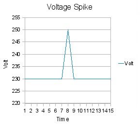
In the following characteristics, the voltage exceeds its upper limit is called as over voltage. Depending on the duration the over voltage durations are like a transient, voltage spike and power surge. The following graph shows the variations between the time and voltage. When the voltage is below the fixed voltage is said to be as under voltage.
Over Voltage Protection
Over Voltage and Under Voltage Circuit Using Comparator
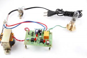
The components required for the block diagram of the comparator circuit is the power supply, step down transformer, bridge rectifier, two preset pins, comparators, voltage regulator, relay, buzzer and AC current. This circuit is planned to expand a low voltage and high voltage tripping mechanism to protect the load from the damage. Generally, in homes & industries, we can observe that there is a fluctuation in AC power supply takes place frequently. Due to the fluctuations of the AC power supply, the electronic gadgets will damage easily. To overcome this problem we can implement the tripping mechanism of over voltage and under voltage protection circuit.
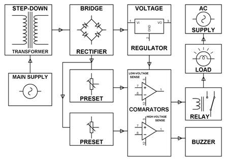
Block Diagram of Over Voltage and Under Voltage Circuit Using Comparator
Circuit Diagram Operation
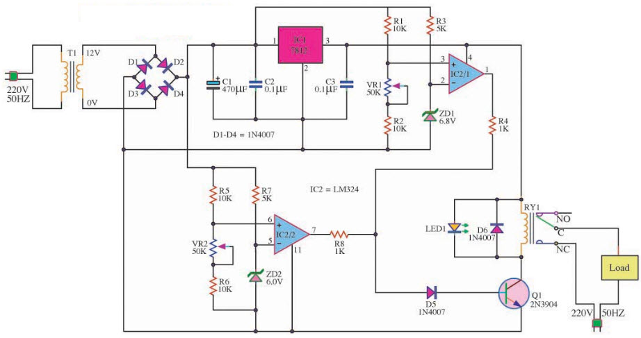
The circuit diagram consists of two IC which are named as LM324, LM7812, NPN transistor, two Zenor diodes, capacitors and LED respectively. In the circuit, we can observe that the input of 220v AC through a transformer T1 and it reduce up to 12v with the help of the bridge rectifier. By using the two capacitors C1 & C2 of power smoothing filters we can convert the voltage, alternating current to direct current.
Circuit of Over Voltage and Under Voltage Protection Using A Comparator
The IC Rex bit is an input pin of IC1 is computing to the 12v power supply is fixed to the IC2. Thus we can consider as an IC op-amp and its pressure act as an IC2/1 is a high voltage detector, high voltage ICs, current works to the transistor Q1 and the relay function works with the cutting of power from the load intensity. The IC/2 is used to detect the lower voltages and with VR1 & VR2 the two components are specified. The LED is used to display the high power & low power over a specified.
Over Voltage & Under Voltage Protection System Using Timer
This is another type of protection system using timer circuit is designed for the low voltage & high voltage protection system load from the damage. From the above circuit, we can observe that in the place of comparator we are using a timer in this circuit. These two timers are delivered an output error to switch the relay mechanism when the voltage violates its arranged limits. Therefore it protects the appliances from the adverse effects of the supply voltage.
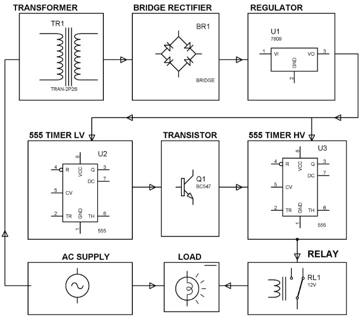
Block Diagram of Over Voltage & Under Voltage Protection System Using Timer
Circuit Diagram Operation
The entire power supply of this circuit is in rectified DC supply and to get the variable voltage the regulated power is connected to the timers & unregulated power is connected to the potentiometer. The two timers configurations are working as a comparator i.e., the input is at the timer to the pin 2, it is less positive than the 1/3 Vcc. The output pin is at the pin 3 which goes high and once the input pin 2 is more positive than the 1/3 Vcc it will be reversed. The potentiometer VR1 is connected to the first timer for under voltage cutoff, the potentiometer VR2 is connected to the second timer for over voltage cutoff.
For the formation of switch logic, the two transistors are connected to the two timers. Generally, we consider that normal operating conditions are between 160 to 250V at this voltage the output of the first timer is considered as a low, thus the transistor 1 is in the cutoff state. Therefore the result will be the reset pin of the second timer is at high which produces the output at pin 3 is high. So that the transistor 2 is in the conducting state and the relay coils are energized. Hence, in the normal conditions, the load will not get interrupted.
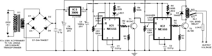
Circuit Diagram of Over Voltage and Under Voltage Protection System Using Timer
In the over voltage conditions are considered about above the 260V at this condition the second timer pin 2 will be high. It produces the low output at the pin 3, therefore the drivers turn the second transistor into the cutoff mode. Thus, the relay coils are de-energized from the main power supply the load gets tripped. In the same way, in the under voltage conditions, the first timer output is high and drives the first transistor mode in the conduction state. Therefore the reset pin of the second timer is at the low condition and the second transistor is in the cutoff mode.
Finally, the relay is operated to isolate the load from the main power supply. The conditions of the over voltage and under voltage positions are also displayed on the LED indication which is connected to the respective timers are shown in the figure.
Application of Over Voltage and Under Voltage
- It is used in the home appliances, industries to control the voltage fluctuations
- Protection of sensitive electronic devices
- Agriculture motors
- Water pumps
Advantages of Over Voltage and Under Voltage
- The price of this circuit is very less and reliable
- It can handle heavy loads up to 7A
- In the abnormal condition automatically the switch is OFF state
- In the safe condition automatically the switch is in the ON-state
- These are highly sensitive
In this article, we have discussed the over voltage and under voltage protection system. I hope by reading this article you have gained some basic information about this article. If you have any queries about this article or about the implementation of the major projects in electrical & electronic please feel free to comment in the below section. Here is the question for you, what is the function of over voltage and under voltage protection system?