In the scope of the electronics domain, we need to deal either with a larger or smaller amplification range of signals. Let us consider the scenario that we need to amplify a signal in the range of millivolts, and this is the signal where the change in volt in correspondence to change in time is very minimal. These signals cannot be amplified using RC coupled amplifier because these signals could not be bypassed through a coupling capacitor. Even the direct coupling method is also not appropriate for this condition. So, to overcome this complexity, a technique is implemented where a signal is divided into many small parts which are also termed as chopping off a signal. And the amplifier used in this circuit is called as “Chopper Amplifier”. Let us see how chopper amplifiers are operated and their importance?
What is a Chopper Amplifier?
A chopper amplifier is an electric circuit that implements a modulation methodology to minimize both the low-frequency noise signals and DC offset conditions in the op-amp. These days of chopper amplifiers use various scenarios to accomplish this, but the main principle is that a chopper amplifier works in combination with that of the main amplifier. These amplifiers use switches for modulating and chopping purposes. Then the resultant signal is sent across filters, summed up and fed as input to the chopper and main amplifiers.
Types of Chopper Amplifier
Chopper amplifiers are mainly classified as mechanical, non-mechanical, and differential chopper amplifiers. Let us have a detailed look at these amplifiers and their operating principles.
Mechanical Chopper Amplifier
To provide conditions like minimal drift and offset conditions, chopper amplifiers are the prominent solution. Bipolar amplifiers provide offset voltages in the range of 25 microns to 0.1 microvolts. Offset voltages which are minimal of 5 microvolts having essentially no significant drift can be attained through these amplifiers.
The mechanical chopper amplifier working principle can be explained as follows:
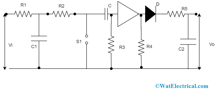
When the switches in the circuit are at auto-zero position (which means in Z), then C2 and C3 capacitors get charged to the input and output amplifier and offset voltages correspondingly. Whereas when the switches are at sample means “S” position, then input voltage is connected to the output voltage in the path that consists of C2, C3, R1, R2, and R3. The chopping frequency is selected in the range of between hundreds and thousands of kHz. As this is the sampling system, the chosen input frequency has to be less than that of half of the chopping frequency, with these errors can be eliminated those arise because of the aliasing effect. In this circuit, the path of R1 and C1 supports as antialiasing filter. It is even believed that when the circuit reaches a steady-state, there will be only less amount of charge transfer at the time of switching cycles. The ranges of load resistance and the output capacitor are selected so that output voltage droop is less at the time of the auto-zero cycle.
The below picture shows the chopper amplifier circuit diagram:

Mechanical Type
Non-Mechanical
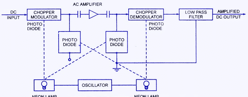
When compared with mechanical kind of chopper amplifiers, non-mechanical type employs either photoconductors or photodiodes for the purposes of modulation and demodulation. When no light is illuminated on the photodiode, then there will be no current flow across the circuit. And when there is light illumination on the photodiode, current flow happens and the resistance is decreased. This scenario corresponds to a switching functionality.

Non Mechanical
In the above picture, an oscillator consists of two neon type of bulbs, where these function on the oscillations of photodiodes PC1, PC2, PC3, and PC4. The first lamp flickers light on PC1 and PC2. Whereas lamp 2 flickers light on the diodes PC3 and PC4. When there happens light illumination on the PC1 capacitor starts to charge thus lessening the resistance value. And when the light illumination is on PC3, input flows through this. So, alternate illumination of PC1 and PC3 generates a square wave. This wave is fed as input to the AC amplifier and it amplifies the signal. While the other diodes PC2 and PC4 regains the DC signal and allows complete charge of the capacitor to the range of output voltage. In the end, using a low pass filter all the noises are ripples are eliminated and the output is DC signal which is amplified.
Differential Amplifier
This is mainly implemented for the measurement of EEG waves. This has a transformer where a chopper vibrator is connected as an input to it. The transformer’s center tap performs as one terminal and the chopper switch as other. The gain for the signal is provided by the amplifier and from the demodulator, DC signal can be received and it is amplified.
Chopper Amplifier in Biomedical Instrumentation
In the domain of biomedical, at the time of recording biopotentials the two obstacles that many people come across are drift and noise. Noise occurs because of recording devices or when the patient moves. While drift is a change in the baseline that is generated because of different thermal impacts. In a DC amplifier, when the input is ‘0’, then it encounters either sudden peak or shift. So, in this condition chopper amplifier works at the best by resolving the drift problem in DC amplifiers.
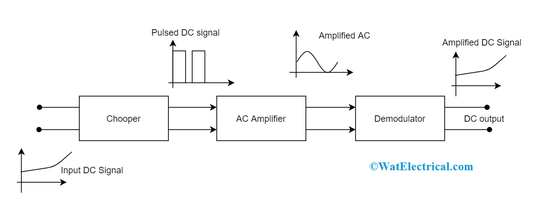
The fundamental diagram of a chopper amplifier used in biomedical instrumentation is shown as:

Basic Chopper Amplifier
The DC signal is fed to the first block of the circuit and it transforms it as AC signal. Then in the next block, amplification of the chopped AC signal is done and finally in the demodulator section AC signal is transformed to DC signal.
Applications
There are wide applications of chopper amplifiers and few of those are as follows:
- These devices are utilized as battery chargers
- Used in battery controlled electric cars
- Implemented in railway tractions
- Can be used for DC voltage amplification purposes
- In brushless DC torque motors, chopper amplifiers are used as drivers and as stepper motors in the actuator devices
- Also regulates the speed in DC motors
- Operated as variable frequency drivers and class D type of electronic amplifiers
- Converted capacitor filters
- Used in the applications where a minimal range of voltages are necessary.
So, this is all the concept of the chopper amplifier, its working principle, and how it is used in biomedical instrumentation. Chopper amplifier has an array of benefits and applications in many domains. Apart from the basic concepts of the chopper amplifier, also know about the other types like what are step up and step down chopper amplifiers?