It was known that in the year 1745, Kleist discovered that charge can be accumulated by accomplishing the connection between electrostatic generator through a wire to water in a glass jar. The component that is used to store the charge is called a capacitor. These capacitors are categorized as non-electrolytic and electrolytic depending on their polarities and dielectrics. The necessary amount of capacitance is obtained when these capacitors are connected in a certain format. There are various types of connections in arranging the capacitors and the fundamental ones are series and parallel connections. And today, this article explains capacitors in series connection, their formula, examples in this connection, and applications.
What are Capacitors in Series?
In various applications, many capacitors are connected together to serve the specific requirement. Connecting multiple capacitors will operate as a single capacitor and the output of the capacitor is based on how they are connected and the performance of each individual capacitor.

Capacitors in Series
When the capacitors are connected in a series format, then the resultant output equals the single capacitor. The output is the entire sum of spacing that exists between the capacitor plates of each one.
Analysis of Capacitors in a Series Connection
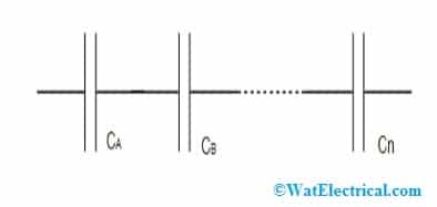
The below picture shows the functional block of capacitors in a series connection.
When this functional block is connected with any voltage source, then every individual capacitor attempts to store a similar amount of charge in it. This corresponds that the total charge is uniformly distributed for all the capacitors no matter what their capacitances are. The series capacitors equation for charge stored in each capacitor is given by
Qtotal = QA = QB = QC = ……..= Qn
To know why the capacitor stores an equal amount of charge and this equals the total charge in the entire series connection, let us consider that every capacitor stays uncharged at a specific time. So, when the voltage is applied for the functional block, then a similar amount of current flows across each capacitor, and finally, a change shift takes place.
As discussed in the above section that electrons are transferred between capacitor’s plates, which means that charge accumulated by any capacitor plate is received from its adjacent plate, and because of this every capacitor stores a similar amount of charge. But, it does not mean that voltage for every capacitor is not the same and it is known by the below formula that is
Vn = Qn/Cn
Here, Cn and Vn are the capacitance and voltage for the capacitor and Qn represents the accumulated charge for each capacitor.
When we apply the KVL principle to the series-connected functional block, then the voltage through the block is equal to the total value of voltages all across every capacitor and this is represented as follows:
Vtotal = VA + VB + ……Vn
When the above formula is substituted in the charge stored in each capacitor, then it gives the capacitors in the series formula which is
Qtotal/Ceq = [(Qtotal/CA) + (Qtotal/CB) + …+ (Qtotal/Cn)]
1/Ceq = [(1/CA) + (1/CB) + …+ (1/Cn)]
The above equation can be explained as that the equivalent capacitance’s reciprocal value equals to the sum of every individual capacitor’s reciprocal value which is connected in a series way.
Capacitors in Series Example
Here is the example to find the entire capacitance value for the below
- Two capacitors having the capacitance value of 50 nF
- One capacitor has 500 nF capacitance which is in series connection with the capacitor of 1 µF
Answer (i)
Here, CA = 50 nF and CB = 50 nF
By applying the capacitors in series formula, then
Ctotal = [1/[(1/CA) + (1/CB)]]
Ctotal = [1/[(1/50) + (1/50)]]
Ctotal = 25 nF
So, the total capacitance is 25 nF
Answer (ii)
CA = 50 nF and CB = 50 nF
By applying the capacitors in series formula, then
Ctotal = [1/[(1/CA) + (1/CB)]]
Ctotal = [1/[(1/500) + (1/1000)]]
Ctotal = 333 nF
So, the total capacitance is 333 nF
Precautions
As most users of a series connection of capacitors are in circuit designs like oscillators, this connection is also applicable in increasing the functional voltage levels.
1). When two or more capacitors are series-connected, then the problem here is that they both do not divide voltage similarly and this causes variances in the leakage current, and this happens mainly in the case of electrolytic capacitors. This means there is some variation between the capacitors and because of this one device might have high voltage levels that cause the damage of either one or both the capacitors.
This damage takes place when capacitors are arranged in a series connection. A minimal amount of leakage current might take place at the time of manufacturing or when the aging period between the two capacitors does not match.

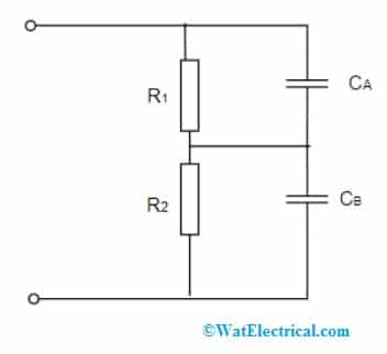
Capacitive Voltage Divider Circuit
2). High-value resistors are to be included in the design of series connections of capacitors and this allows for voltage sharing equally between the capacitors. And these resistors operate as potential dividers. Resistors having a value of either 100kΩ or more, but sufficient because the voltages should reliably perform as dividers for the capacitors. This is one of the crucial precautions to be considered.
3). The other safety measure to be noted down is that the resistor values must be chosen in the way that the amount of current that flows through those resistors should be nearly 10 times more than the leakage current. With this approach, voltage is allowed to be shared equally between the capacitors in a series connection.
This is the approach that is mainly followed for electrolytic capacitors. So, these are the main precautions to be considered while connecting capacitors in a series connection.
Applications
This section explains the applications of capacitors in series. A few of the prominent applications are as below:
Capacitive Voltage Divider – A voltage divider is considered as the device where that helps in dividing the applied voltage into a corresponding number of voltage outputs at the specified ratio. And this voltage divider is designed using reactive components such as capacitors and resistors.
So, when capacitors are placed in a series connection and application of voltage is done, then the voltage across every individual capacitor is not the same but is based on the capacitance values. The below picture shows the capacitive voltage divider connection.

Capacitors as Voltage Divider in Series Connection
To be more accurate, the ratio of the voltage across each capacitor is completely inverse to the capacitance values ratio of every capacitor those are in series connection. And this arrangement is only applicable for AC circuits because capacitors do not allow DC signals to pass through them and also, they have a specific amount of leakage in voltage.
Higher Working Voltage – In order to deal with increased voltage levels, it is more recommended to use capacitors in series connections.
For instance, let us consider that a 5kV supply is to be filtered using capacitors and all the capacitors have a similar rating of 1kV. Here, when four or more capacitors when connected in series, then the voltage is equally divided between each capacitor, and it does not exceed the maximum rating.
The other example of capacitors in series connection is that block of capacitors when connected in series can be used as a substitute for car battery. As the highest voltage rating is only 2.7 volts, when six supercapacitors are connected in series, then the functional voltage of the block is increased to the level which is suitable for automobile usage. With this replacement, the main benefits one can have is less weight.
On the whole, capacitors in series summary can be stated as that the entire capacitance value of the circuit having series-connected capacitors equals the reciprocal of the sum of each capacitor in the connection.
Please refer to this link to know more about Capacitor MCQs.
And this article has explained capacitors in the series of functional circuits, how the circuit works, its equation, a few solved examples, and applications. Also, know what is the safety to be followed while using capacitors in series?