For analog & digital devices, system noise has become a major problem so they have become very sensitive to disturbances from signal lines & power. So the capacitors like decoupling and bypass within a circuit are used very close to the IC power pins to provide high transient current to an integrated circuit & decrease power ripples. Analog circuits like audio amplifiers produce a cracking noise or hum throughout their operation whereas digital circuits like microcontrollers produce random & inconsistent behavior because of the not stable input. So, this article discusses an overview of a decoupling capacitor, its circuit, its working & its applications.
What is a Decoupling Capacitor?
A passive component that is used to provide high transient current to an IC within a circuit & decrease power ripples is known as a decoupling capacitor. Generally, this capacitor is located parallel to the power source & the load used in the circuit. To reduce the voltage disturbances for every IC, these capacitors must be connected very close to the IC. Generally, the decoupling capacitor’s function is to store energy, remove high-frequency noise, stabilization of voltage, and DC power supply to active devices.
Decoupling Capacitor Circuit
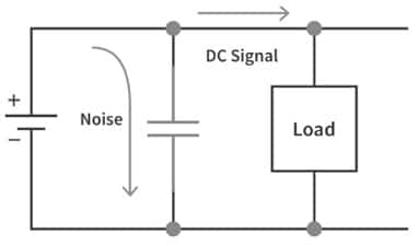
The circuit diagram of the decoupling capacitor is shown below. This capacitor in the circuit must be connected between the power supply & the load or IC in parallel as shown in the following circuit. This capacitor is used to decouple the signals from DC to AC or vice versa. This capacitor removes the noise & distortion of power to protect the IC by simply providing a very pure DC supply.
Here, there are certain standards for selecting the decoupling capacitor value. The value of a decoupling capacitor with low-frequency noise must typically range from 1 µF – 100 µF The decoupling capacitor with high-frequency noise typically ranges from 0.01 µF – sheet. These capacitors should be connected directly to a low-impedance ground plane always for efficient operation.
To maximise the effectiveness of decoupling capacitors, proper placement is crucial. These capacitors should be located as close as possible to the power supply pins of ICs or sensitive components. Placing them near the components minimise the length of the power traces, reducing inductance and providing a low-impedance path for high- frequency current.
Decoupling Capacitor Circuit
Working
Once a decoupling capacitor is connected to the circuit, it will perform these functions. If the input voltage of the circuit drops, then the capacitor provides sufficient power to an integrated circuit to maintain the stable voltage. If the input voltage enhances, then the capacitor absorbs the surplus energy and supplies it throughout the IC and again it maintains the stable voltage. So when you connect a decoupling capacitor next to an integrated circuit, then you will be able to defend these sensitive chips by simply filtering out any surplus noise & creating a stable power source.
These capacitor processes are very significant in logic circuits because if a logic gate works with 5V. If the supply voltage goes over 2.5V then it will read like a High signal & if the supply voltage goes under 2.5V then it will read like a Low signal. As a result, if there is a noise within the voltage supply, then it will activate highs & lows within the logic circuit, therefore the DC Coupling capacitor is extensively utilized for logic circuits.
How to select a decoupling Capacitor ?
When selecting decoupling capacitors, several factors should be considered. The capacitance value is a key parameter that determines the capacitors’ ability to filter noise effectively. It is recommended to consult the datasheet of the IC or follow manufacturer guidelines to determine the suitable capacitance value. Additionally, the capacitors’ voltage rating should exceed the maximum voltage present in the circuit.
Decoupling Capacitor Vs Bypass Capacitor
The difference between decoupling capacitors vs bypass capacitors includes the following.
Decoupling Capacitor | Bypass Capacitor |
| A decoupling capacitor is used to Isolate/decouple two different circuits. | A bypass capacitor is mainly used to avoid noise from entering the system by supplying it to the GND. |
| This capacitor simply stores energy & dissipates this energy back into the power rail for maintaining the smooth current supply. | This capacitor provides the AC signal return path toward the switch among the power & GND rail. |
| This capacitor creates a low-impedance lane for the AC signal. | This capacitor removes surplus noise from cables or an electronic system. |
| This capacitor must be located in parallel between the power supply & the load or IC to one another. | This capacitor must be located between the power supply & Ground to decrease both the noise of the power supply & the spikes that result over the supply lines. |
| This capacitor is mainly designed for smoothening the signal by simply stabilizing the distorted signal | This capacitor is mainly designed to shunt noise-based signals. |
| It is a significant component in logic circuits. | It is used in almost all analog and digital circuits. |
| The capacitance value for low frequency ranges from uF-100uF and for high frequency, it ranges from 0.01uF – 0.1uF. | The capacitance value must be 73uF. |
Decoupling Capacitor Types
Decoupling capacitors are available in different types like ceramic, aluminum polymer, tantalum, and aluminum electrolytic capacitor.
Ceramic Capacitors
Ceramic capacitors are decoupling capacitors that store a charge of electricity. This is a fixed-value capacitor wherever the ceramic material in this capacitor performs as a dielectric. This type of capacitor includes a number of alternating ceramic & metal layers that work like an electrode. In this capacitor, the ceramic material composition describes the electrical behavior with its applications. The advantages of these capacitors are low ESR & ESL and the main drawback is a limited range of capacitance. These capacitors are good at maximum frequency applications.
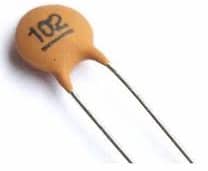
Ceramic Capacitor
Please refer to this link to know more about Ceramic Capacitors.
Aluminum Electrolytic Capacitors
An aluminum polymer capacitor is used to store electric charge. These are generally composed of an insulating layer coated with aluminum foil, a saturated paper sheet with electrolyte & aluminum foil. These capacitors are most frequently polarized. The advantages of this capacitor are; low cost and high capacitance. Its disadvantages are; temperature wears out and degrades over time, large size, and high ESR. The applications of this capacitor are; used for large bulk storage and consumer products.
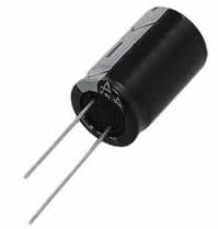
Aluminum Electrolytic
Aluminum Polymer Capacitors
An aluminum polymer capacitor is made with a separator sheet that is saturated through a polymer-made electrolyte. After that, this sheet is arranged in between aluminum foils. The advantage of this capacitor is very low ESR, the disadvantage is fast degradation > 105⁰C and these are used in CPU core regulators.
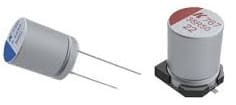
Aluminum Polymer
Tantalum Capacitors
Tantalum capacitors utilize tantalum metal for the anode and these capacitors have long-term stability & superior frequency characteristics. These capacitors have almost unlimited shelf-life, reliability, and high capacitance density. The dielectric material of these capacious will be in the tantalum oxidized form. The advantages of these capacitors are; extremely steady over time, low ESR & ESL. The disadvantages of these capacitors are; Fire risk within reverse voltage and 50V of limited rated voltage. The applications of these capacitors are; sample & hold circuits which depend on low leakage current to attain long hold periods, communications, military & aerospace industries, advanced electronic devices, submarine cables, televisions, civil appliances, etc.
Tantalum Capacitor
Calculation of Decoupling Capacitor
The decoupling capacitor’s capacitance ‘C’ necessary by an integrated circuit can be calculated by the following decoupling capacitor formula.
C.ΔU = 1. Δt
‘⊿U’ is the acceptable decrease in the voltage of the actual power bus.
‘ I’ is the maximum necessary current(A).
‘⊿t’ is the time duration for this necessary capacitance.
Advantages
The advantages of decoupling capacitors include the following.
- These capacitors help in maintaining low dynamic impedance from the individual voltage supply of IC to GND.
- These capacitors provide maximum transient currents to an integrated circuit.
- It reduces power ripples.
- These are utilized to filter out voltage spikes & pass only through the signal’s DC component.
- It is perfect for analog circuits.
- It reduces digital circuit noise, RF noise & common mode noise of other power supplies & single-ended noise
- This capacitor performs like a backup and provides charge once the voltage dips.
- These capacitors prevent fast voltage changes by performing as electrical energy reservoirs.
Applications
The applications of decoupling capacitors include the following.
- This capacitor is used for decoupling or isolating two different circuits.
- These capacitors are used in power supply signals o suppress high-frequency noise.
- This capacitor simply provides a bypass lane for transient currents, rather than supplying throughout the common impedance.
- These are utilized to oppose disturbances from different sources
- These are used to decouple the AC signals to DC.
Know more about DC Circuit MCQs.
Thus, this is an overview of a decoupling capacitor – working, advantages & its applications. So selecting a decoupling capacitor with adequately high self-resonant frequencies mainly depends on the operating frequency & bandwidth of the signal. Here is a question for you, what is a coupling capacitor?