The theory in the electrochemical procedure, metals such as aluminum, niobium, cadmium, and others create an oxide coating that obstructs the actual flow of current directions but allows to flow in the opposite paths. This phenomenon was initially observed by Johann Buff in the year 1875 and its implementation was done by Ducretet. The manufacturer of accumulators namely “Charles” came to know that the oxide coating stays stable in the case of alkaline and neutral electrolytes when there is no power also and for this he received the patent in 1897 for a borax type of electrolytic capacitor. From then, various types of electrolytic capacitors came into existence, and today, the article completely discusses its working, features, types, and advantages.
What is Electrolytic Capacitor?
The foremost definition of an electrolytic capacitor is that it is a polarized capacitor that utilizes an electrolyte to gain a higher capacitance value than that of other types in the capacitor. The electrolyte can be a gel/liquid having increased ionic concentration. And almost every electrolytic capacitor has polarized nature which specifies that positive terminal voltage is high than that of negative terminal voltage level.
The advantage of having a high capacitance level in electrolytic capacitors arrives with multiple drawbacks also. And few of those downsides are huge leakage current, value tolerances, similar resistance value in series connection, and lesser life span.
The electrolytic capacitors can be of solid polymer type or wet electrolyte type which are usually designed with aluminum and tantalum. And supercapacitors are the other unique type under electrolytic capacitors having the capacitance value of a few hundreds to thousands. And the capacitance range lies in the range of 1 µF to 48 mF having the voltage range of some hundreds of volts.
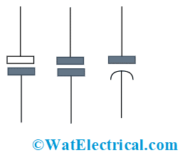
As discussed, electrolytic is a type of polarized capacitor and the symbol of the capacitor implies electrolytic capacitor polarity. Polarity in the capacitor is crucial to make sure that the device is properly fitted into the circuit and also ensures that it is not in reverse biased condition. The below picture shows the electrolytic capacitor symbol.

Electrolytic Capacitor Symbol
There are different types of schematic symbols used for the representation of electrolytic capacitors. As per the above picture, the first one represents the usage of devices in European circuits, the second one is used in US circuits and the third is an older version of the representation. Whereas in a few schematics, the ‘+’ sign is not displayed because it is already clear what is the plate polarity.
Construction and Properties of Electrolytic Capacitor
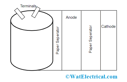
In the construction of electrolytic capacitors, two thin aluminum foils are used where one of the layers is coated with an oxide layer and this acts as an insulator. As because the aluminum foil is used for coverage, the device can also be termed an aluminum electrolytic capacitor. In between the two plates, a paper sheet which is soaked in an electrolyte is placed and then the plates are thoroughly wounded within each other and later kept in a container.
As a first step in the construction, etching is done for foils which make them rougher, and it helps in increasing the surface area. The etching process also helps in attaining a high capacitance valve in the specified area.
The second stage is the development of anode where involves creating a thin layer of Al2O3 on the anode and this creates a difference of anode corresponding to the cathode
Then the entire capacitor substance is rolled on a winding instrument. Here, all the four layers that are anode coil and its paper screen, cathode foil, and its paper screen are all wounded together. Because of using paper screens, electrodes are protected from getting touched and shorted. After the wounding is done, the device is taped so that it prevents unwinding. Later, the capacitor is infused along with the electrolyte, and this is done through the immersion procedure under pressure.
As discussed in the first step that aluminum is used as an electrolyte, using this will allow the capacitor to maintain necessary properties such as required temperature level, voltage rating, and others.

Construction
This is the procedure of constructing an electrolytic capacitor.
Properties
The properties of electrolytic capacitors are mentioned below:
- Aluminum type of electrolytic capacitors offer increased capacitance levels when compared with the ceramic type of capacitors
- These devices are polarized which means that they are to be located only in one way round the circuit
- Electrolytic capacitors are to be operated below the rated functional voltage level, or else this might impose high risks
- Good tolerance ability having the range of -50% to +100%
- These can function properly at frequency ranges and are not suitable for the frequency above the range of 50 – 100 kHz
Types in Electrolytic Capacitor
The combination of anode substances and electrolytes that are used in capacitors creates different types of electrolytic capacitors. A few of those types are outlined in this section.
Aluminum Type
These are of two types which are
- Wet aluminum electrolytic capacitors
- Dry aluminum electrolytic capacitors
A brief on this type of capacitors is explained in the above section.
Tantalum Type
This is the passive substance of electric circuits having a ball-sized tantalum substance acting as anode and this coated with an insulating oxide substance. This covering allows for forming dielectric and enclosed by solid/liquid electrolyte thus forming a cathode.
As the dielectric layer is very narrow and has increased permittivity, the tantalum capacitor is thus differentiated from another type of electrolytic capacitors, and these are expensive too.
These capacitors are fundamentally polarized devices and if it works in reverse voltage condition, it might cause damage for the device. Bipolar/non-polar capacitors can be constructed using the series connection of polarized capacitors having that the anodes are made to be in opposite paths.
Niobium Type
This is also a polarized and passive capacitor where its anode is constructed by a niobium substance/niobium monoxide and on top of it niobium pentoxide operates as the capacitor’s dielectric material. And then a solid electrolyte which is on the top of the oxide layer acts as a cathode for the capacitor.
The availability of niobium electrolytic capacitors will be in the form of an SMD chip, and these possess a similar level of voltage and capacitance to that of tantalum chip capacitors. These capacitors are perfectly functioned only with DC voltages and in the correct polarity directions. In the cases of higher voltages and reverse voltages, the dielectric gets damaged and so does the capacitor as well.
Non-Electrolytic Type
Here, the dielectric substance that is used in the capacitors is in non-electrolytic form and this type of capacitor also has multiple advantages. This is also termed bipolar capacitors.
These are the main types of electrolytic capacitors.
How to Read Capacitance Value?
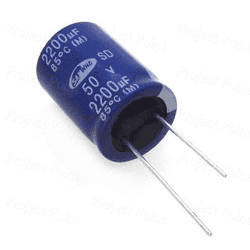
For through-hole capacitors, all the readings such as the highest voltage rating and capacitance values are on the packaging.
When it is printed as 5.0µF 30V, then the capacitor’s capacitance value is 5.0µF with the highest functional voltage rating as 30V and the device should not be operated above the specified value.
In the case of surface-mounted electrolytic capacitors, the printing on the enclosure will be in two forms. In the first form, the capacitance and voltage ratings are clearly printed in µFarads and volts.

Electrolytic Capacitor With Markings
Example: “4.8 30V” implies that capacitance value is 4.8µF and voltage is 30 volts.
Whereas in the second form, after number numbers, a letter is written, and this letter signifies to voltage rating as per the below-mentioned table. Of the three numbers, the first two imply value in picofarads and the last number is the total number of zeroes.
Example: “E486” represents that 48000000 pF = 48000 nF = 48 µF
| Voltage Value | Letter |
| 2.5 | e |
| 4 | G |
| 10 | A |
| 16 | C |
| 25 | E |
| 35 | V |
| 50 | H |
Characteristics of Electrolytic Capacitor
While choosing a capacitor, a few of the characteristics that are to be considered are:
- Drift – Typically 20%
- Tolerance – High tolerance in the range of -20% to +80%
- Frequency response – Electrolytic capacitors have a minimum frequency response
- Equivalent series resistance – These capacitors are employed in circuits when there are high current levels
- Leakage – Shows high leakage levels
Advantages & Disadvantages
The advantages of electrolytic capacitors are:
- The devices can be quickly charged and also accumulation of energy is so quick
- Dissipation of accumulated energy is also so quick
- Minimal losses when compared with other types of capacitors
- Long lifetime
- Minimal maintenance can be sufficient
The disadvantages of electrolytic capacitors are:
- The devices get easily damaged when operated at high-temperature levels during soldering
- Voltage transients
- Gets dried out easily
- Exhibits internal power dissipation
- Reverse voltage
Applications
The applications of electrolytic capacitors include the following.
- Electrolytic capacitors are used for decreasing voltage instabilities in many filtering appliances
- Used for the purposes of filtering noises and also for decoupling in the power supplies
- Used for accumulation of energy in flashlamps
- Employed for coupling various signals in between the amplifier phases.
Know more about Capacitors in Series.
So, this is the complete description and explanation of electrolytic capacitors. Even though there are drawbacks in implementing the capacitors in electric circuits, but because of their advantages, they are extensively employed across various applications. Know, how an aluminum electrolytic capacitor is re-formed?