The first moving coil galvanometer was invented in 1820 by Danish physicist Hans Christian Oersted as an improved version of the astatic galvanometer he had created a few years earlier. Since then, the design has been modified and improved to become smaller, more accurate, and more sensitive. The instrument is still widely used today in laboratories and factories all over the world for all types of electrical measurements. This article discusses an overview of a moving coil galvanometer and its working with applications.
Moving Coil Galvanometer Definition
A moving coil galvanometer is a type of galvanometer that uses a loop of wire to measure the electric current. The length of the wire is small compared to the size of the loop, and it moves freely across a magnetic field.
An electromotive force (emf) is generated in the coil by any change of current in this wire which creates a magnetic field. A small needle on the galvanometer moves as this magnetic field changes and indicates the strength of the field by how much it deflects the needle.
Moving Coil Galvanometer
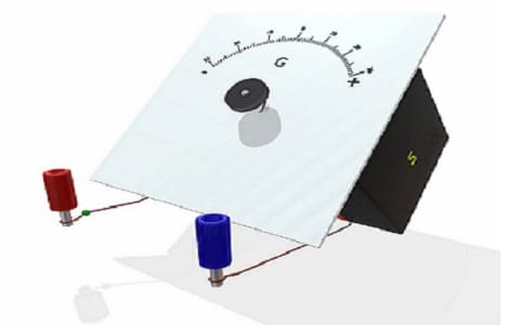
This measuring device consists of a coil of wire suspended between the poles of a permanent magnet. When an electric current passes through the coil, it produces a torque in response to this magnetic field. This torque is detected by a needle attached to the coil. A galvanometer works by detecting the movement of its needle. Please refer to this link for the ballistic galvanometer.
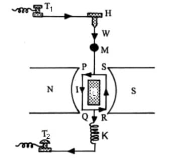
Moving Coil Galvanometer Construction
The moving-coil galvanometer functions in a manner similar to the Wheatstone bridge, but has several distinct advantages. The Wheatstone bridge is usually constructed with the moving coil attached to one of the resistors (the load resistor). In this case, the load resistor must be very much larger than the resistance of the galvanometer coil, because the current through both resistors is equal at all times and thus need not be equalized by an amplifier. Since the load resistor must have a large resistance and a large physical size, it is not practical to use this type of galvanometer as a voltage meter in many cases.
Mooving Coil Galvanometer Construction
The moving-coil galvanometer has a more sensitive design because it uses an amplifier to make up for any difference in current between the two coils. The moving-coil galvanometer is especially well suited for measuring high voltages and currents (or low electrical resistance) because its construction allows for the amplification of small signals from a small-diameter coil.
This moving coil galvanometer is used in applications that require very high sensitivity. In addition to the standard versions, this model can be operated in different modes of operation. These include:
- DC mode with a high amplification ratio.
- AC mode with a low amplification ratio.
- AC mode with a high amplification ratio.
These characteristics make it possible to develop a wide range of applications. For example:
- Compensating for errors in the system or in the positioner (in the case of AC and DC modes).
- Determining the position of moving parts on CNC machines (in the case of AC mode).
Moving Coil Galvanometer Working Principle
The working principle of this instrument is basically similar to that of the common galvanometer. The moving coil galvanometer has two coils located inside a vacuum chamber. One is the primary coil and the other is the secondary coil. The two coils are placed in parallel with each other, which forms a magnetic circuit. When there is an electric current flowing through the primary coil, a magnetic field (also known as Ampere’s law) is produced as well.
This magnetic field induces an electric potential difference across the secondary coil when it cuts through the magnetic field of the primary coil.
A light beam can pass through an aperture situated at one end of the cylindrical tube where these two coils are placed. When there is no current flowing through any of these coils, the light beam remains static at one end of this aperture. As soon as a current starts flowing through either of these coils, this light beam starts moving towards another end of the cylindrical tube.
The reason behind this phenomenon is that these two coils are wound in such a way that they produce a magnetic field, which in turn produces an electric field and hence an electromagnetic wave. This in turn causes the motion of the light beam towards another end.
Moving Coil Galvanometer Theory
Consider the following single turn rectangular PQRS coil where the current ‘I’ supplies throughout the coil. The plane of the coil in a radial magnetic field is always similar to the magnetic field. Thus, the sides of this coil-like QR & SP are always parallel to the magnetic field. Thus, they do not experience any force.
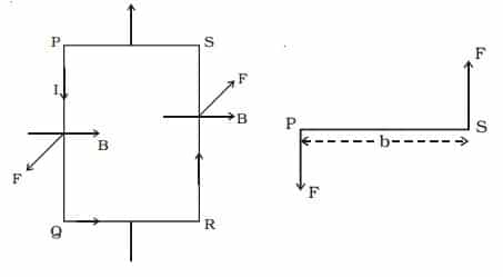
Galvanometer Theory
The length of PQ & RS = l whereas the breadth of the coil is PS & QR = b.
Force on PQ side F = BI (PQ) => BIl.
According to the left-hand rule of Fleming, this force is standard to the plane of the coil and works towards the outside.
Force on RS side F = BI (RS) => BIl.
So, this force is standard towards the plane of the coil & works inside.
This two equivalent and reversely directed parallel forces including different action lines constitute a couple & turn aside the coil. If the turns within the coil is ‘n’,
The deflecting couple moment is nBIlxb
The deflecting torque moment is nBIA
Once the coil deflects, then the suspension wire can be twisted. In the description of elasticity, a restoring couple can be set up within the wire. So this couple is directly proportional to the twist. If the angular twist is ‘θ’, then,
The restoring couple moment is ‘Cθ’
Where ‘C’ is the restoring couple for each unit twist.
The deflecting couple at balance is equal to restoring couple like nBIA = Cθ
nBIA = Cθ
I = (C/ nBA) θ
I = K θ
Where ‘K’ = C/ nBA, is the constant of the Galvanometer.
So, I α θ, because the deflection is directly proportional to the flow of throughout the coil, so the scale is linear & is adjusted to provide the current value directly.
Sensitivity of Moving Coil Galvanometer
The sensitivity of a moving coil galvanometer is a measure of the amount of change in current that occurs when a small, magnetic field is applied to the coil. The sensitivity of the galvanometer is determined by its resistance at different frequencies, and it’s measured in ohms or Ω. A typical galvanometer has a resistance range of 1Ω to 20,000Ω and a sensitivity range of 0.01Ω to 10mΩ.
The sensitivity of a moving coil galvanometer refers to how strongly it responds to the applied magnetic field. A higher sensitivity means that the galvanometer will respond more strongly to an applied magnetic field.
Current sensitivity of a Galvanometer
The galvanometer current sensitivity is, once unit current flows throughout the galvanometer then the deflection will be generated. So, if it generates huge deflection for a small amount of current then a galvanometer is said to be sensitive.
In a galvanometer I = (C/nBA) θ
The sensitivity of current θ/A = nBA/C
The galvanometer current sensitivity can be increased through
By increasing the no. of turns, magnetic induction, and area of the coil and also by decreasing the couple for each unit twist of the suspension wire.
This describes why the phosphor-bronze wire is utilized like the suspension wire which has a tiny couple for each unit twist.
Voltage Sensitivity of a Galvanometer
The galvanometer’s voltage sensitivity can be defined as the deflection for each unit voltage.
Voltage sensitivity θ /V = θ/IG => nBA/CG
From the above equation, ‘G’ is the resistance of the galvanometer.
Here, the increase in current sensitivity does not automatically increase the sensitivity of voltage.
Once the no. of turns is doubled, then-current sensitivity can also be doubled although increasing the no. of turns will increase the resistance (G). So voltage sensitivity remains stable.
How Moving Coil Galvanometer is Converted into an Ammeter?
A moving coil galvanometer is used to detect the current flow within an electrical circuit. It is a very sensitive instrument so a large current cannot be supplied throughout the galvanometer, because it may harm the coil. But, a galvanometer (G) can be simply converted into an ammeter (A) by connecting a low resistance in parallel with it.
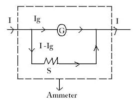
Conversion of Galvanometer to Ammeter
Thus, when large current supplies within a circuit, a small portion of the current flows throughout the galvanometer & the remaining portion of the current supplies throughout the low resistance. So the low resistance which is connected in parallel through the galvanometer is known as shunt resistance.
Here, the shunt resistance value mainly depends on the portion of the whole current necessary to be supplied throughout the galvanometer (G).
Once the max current ‘Ig’ is supplied throughout the galvanometer then the current will provide full-scale deflection within the galvanometer.
So, the resistance of the Galvanometer is ‘G’
Shunt resistance is ‘S’
The flow of current within the circuit is ‘I’
The flow of current throughout the shunt resistance is Is = (I-Ig)
When the shunt resistance & galvanometer are parallel, then there will be a common potential.
Ig.G = (I-Ig)S
S = G (IG/I-IG)
The shunt resistance will be extremely small as ‘Ig’ is simply a portion of I.
The ammeter’s effective resistance ‘Ra’ is
1/Ra = 1/G+1/S
Ra = GS/G+S
Here, ‘Ra’ is extremely low & this describes why an ammeter must be connected within series. Once it is connected in series, then the ammeter does not significantly modify the resistance & current within the circuit. So an ammeter is said to be a deal that has zero resistance.
Similarly, the moving coil galvanometer can be converted into a voltmeter by connecting a high resistance ‘R’ in series with it.
So, the effective voltmeter resistance will be
Rv = G+R
Advantages
The advantages of moving coil galvanometer include;
- High resolution, low noise, low distortion, high signal-to-noise ratio
- Convenient for a pulse and frequency detection.
- Very low power consumption (0.5 mW)
- Small size, lightweight (2.2 g), reliable operation over a wide range of temperatures (-30°C to +70°C) and humidity (10% to 95%).
- It can be used in applications where a high degree of accuracy is required.
- They are sensitive to high-frequency changes in magnetic field strength and thus can detect changes in current as small as 10%. In general, the higher the frequency response, the better the data.
- They have a much smaller operating temperature range than resistive-type galvanometers, so they are more suitable for use in applications where a large amount of power must be dissipated to achieve low temperatures (e.g., electric heating elements).
- They can be used with voltages ranging from DC to 5 kV AC, which is less limited than with resistive-type galvanometers. 4. Their sensitivity is insensitive to surface contamination and corrosion.
- Their sensitivity increases with increasing temperature, when the electrical resistance decreases, so the total power required for detection is reduced.
Disadvantages
The disadvantages of moving coil galvanometer include:
- The mechanical design of the moving coil galvanometer can limit its application in some circumstances. For example, a moving coil galvanometer cannot be used to measure currents with frequencies higher than what its mechanical design can withstand.
- They are not as sensitive as a moving-coil electrometer, so they do not work as well when measuring very small quantities of electricity.
- Sensitivity decreases with increasing distance from the source of the signal and increases with decreasing frequency. This means that a lower frequency signal will have less effect on the output of a moving-coil galvanometer than a higher frequency signal.
- It takes a long time for the galvanometer to complete its measurement if the electric current is very weak.
- The moving coil also suffers from hysteresis losses.
- The resistive heating of the coil can cause damage to the device and its surrounding areas, such as melting components and damaging cables.
- The MCG must be shielded due to the large currents involved. The current is generally very large because of the sensitivity of the test and the need to detect small changes in electrical current. Because this current is relatively high, it can damage electronics.
Moving coil galvanometer Applications / Uses
The applications of moving coil galvanometers include:
- Moving coil galvanometers are the most modern of all instruments and are now used by most large manufacturers of scientific instruments.
- Moving coil galvanometers are used in various applications including particle physics, medicine and biology.
- One common application is motor testing. Before a motor leaves the factory, it must be tested to make sure it’s working properly and has no shorts or other problems in its circuitry.
- Moving coil galvanometers are used in seismology to detect slight shifts in Earth’s magnetic field. Typically a number of wires are laid out around the device and a current is passed through the device. This creates an electric field that induces an electromotive force (EMF) on the system, which can be measured by measuring changes in the voltage and current output of the system.
What is the difference between a galvanometer and a moving coil galvanometer?
Many people are confused about the difference between a galvanometer and a moving coil galvanometer. However, it’s important to distinguish between these two types of instruments rather than assume that the terms will be interchangeable.
A moving coil galvanometer is a type of instrument that is used in several different fields and applications, including radio astronomy, meteorology, and an electrometer. Moving coil galvanometers use coils of wire in order to produce an electrical current.
The primary difference between the two types of instruments is in the unit used to measure their resistance. While a moving coil galvanometer uses the ohms law of resistance (which states that resistance equals voltage divided by current), a galvanometer uses the milli ohm law (which states that resistance equals voltage divided by milli ohm).
Know more about Linear Induction Motor.
Thus, this is all about an overview of a moving coil galvanometer and its working with applications. It is one type of instrument used to measure electric currents within a circuit and it is also measured fewer currents even of the few microamperes order. Here is a question for you, what is an ammeter?