Even though the name Charles Wheatstone was popularized, the circuit was actually invented by a well-known mathematician Samuel Hunter Christie. And the circuit was described in the year 1883. The job done by Christie was not known to the public until Whetstone was introduced. Along with the publicity, there was a constructional improvement in the Wheatstone bridge.
From them, the bridge came into more prominence, and it was implemented in many applications. This article helps us in understanding Wheatstone bridge principles, circuit construction, its derivation, drawbacks, and applications.
What is Wheatstone Bridge?
The instrument that is employed to know the unknown resistance through comparison procedure is termed as Wheatstone bridge. By comparing with the value of known resistance, the unknown value is calculated. This device functions on the null deflection principle which means that the resistances ratio is equal and there is no current flow across the galvanometer.
The instrument operates in a similar way to a potentiometer, and this is mainly employed to measure medium resistance values and to know the high resistance values, a sensitive ammeter is also placed in the circuit. The device was initially built to know the unknown resistance values, whereas it can also be utilized to standardize devices such as ammeters, voltmeters, and others using a variable resistance.
Construction & Working
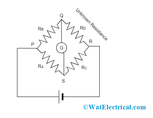
The instrument consists of four arms where three arms have variable resistance, two known resistance, and the other arm consists of unknown resistance (to be known). It also includes an EMF source and a galvanometer. The below picture shows the fundamental Wheatstone bridge circuit.

Wheatstone Bridge Circuit
The device consists of four resistors named RA, RB, RC, and RD. As per the above picture, a voltage source is connected between two points (P and R) which are diagonally opposite to each other and this is considered as battery arm. And in between the other two points (Q and S), a galvanometer is connected to know the current values. The source connected between P and R points is the electromotive source. The amount of current that flows through the galvanometer is known by the level of potential difference which is applied to it. This is the construction of the Wheatstone bridge.
As discussed, the Wheatstone bridge works on the principle of null deflection. We know that a galvanometer is connected between Q and S, and when there is a flow of zero current through it, the bridge is considered to be in a balanced state. So, in this condition, the difference of voltage between Q and A is ‘0’. This corresponds that at the points Q and S, the voltage level is the same.
The balanced state is achieved by varying the known and variable resistance values. Even though in the normal state, for the state of unbalanced Wheatstone bridge some amount of current flows across the galvanometer.
Now, let us know the working procedure of the Wheatstone bridge.
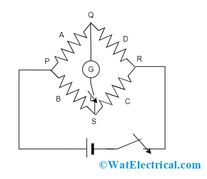
Consider the below picture and it has four resistances A, B, C, and D with an EMF source. Then, two keys M1 and M2 are connected in between the terminals (P and R) and (Q and S). Initially, key M1 has to be connected and then M2 needs to be pressed. Check whether there is any deflection in the galvanometer or not.

Working
If the device shows deflection, then alter the variable resistance value until the deflection reading in the galvanometer is null. If there is no deflection in the galvanometer, then the bridge is considered a balanced Wheatstone bridge. As the galvanometer shows no deflection, there is no current through it. Here,
A/B = C/D
The arm that consists of A and B resistors is termed as ratio arm and to know the value of unknown resistance, the unknown resistor is placed between D and C, and C’s resistance is modified correspondingly to attain a null state. Now, the unknown resistance can be known by
D = (B/A) C
The arms QS and PR are considered as conjugating arms for the bridge due to the reason that when the Wheatstone bridge is in a balanced condition, and if the positions of battery and galvanometer are swapped, then this is shown no impact on the balanced state. The bridge holds increased reliability and gives precise outcomes.
Wheatstone Bridge Derivation
For the balanced Wheatstone bridge, there is no current flow across the galvanometer and at this point IG = ‘0’. So, the current flow across PQ and PR is I1 and the current flow across PS and RS is I2.
As per KVL (Kirchhoff’s voltage law), the voltage drop in the closed-loop is ‘0’ which means the voltage across the loop PQSP is ‘0’. The potential across every resistor in the bridge equals the product of the current flow and resistance across it. So,
I1A – I2C = 0
I1A = I2C
In the same, by applying KVL law at the loop RQSR, we have
I1B – I2D = 0
I1B = I2D
I1/I2 = D/B
By comparing the equations, we have
C/A = D/B
A/B = C/D
This is the term for a Wheatstone bridge in balanced condition.
From the above equation, the Wheatstone bridge formula can also be known which is given by
C = AD/B
Where ‘C’ corresponds to the unknown resistance
‘D’ corresponds to bridge standard arm and
‘A’ and ‘B’ represents the ratio between the arm of a bridge
Sensitivity of the Wheatstone Bridge
In the case of measuring instruments, the crucial aspect to be considered is the device sensitivity factor. The device that shows more sensitivity seems to have high reliability and delivers accurate results.
When all the resistance values are similar or the ratio equals unity, then the Wheatstone bridge is considered to have high sensitivity. For any other values other than the unity and if the resistance values are not comparable, then the bridge sensitivity factor reduces which corresponds that the device holds poor accuracy.
Wheatstone Bridge for Strain and Temperature Measurement
Let us first consider using a Wheatstone bridge for strain gauge measurement.
Strain Gauge Measurement
In general, Wheatstone strain gauge circuits are mostly employed in transducers for the conversion of mechanical strain into electrical signals. Like the basic Wheatstone bridge, the strain gauge Wheatstone circuit also has four resistors which are connected in a diamond format. Mostly, all the terminals are active which increases the transducer sensitivity whereas in some situations, two elements will be fixed resistors and the other two are strain gauges.
The circuit of the Wheatstone bridge strain gauge is constructed by placing a couple of strain gauges on the substance where it will be stressed. So, when pressure is applied, these will get expanded in their width direction. The other couple of strain gauges are placed exactly in 900 direction to the other couple where these will get expanded in the direction of their length.
The simple way of constructing this circuit is to place all the four strain gauges on the surface that has to be measured in a radial direction which has a separation of 900 and all these four should point in a similar direction. The gauges that get expanded in width direction lessens the resistance whereas the gauges that get expanded in length direction augments the resistance.
The connection points for all the four strain gauges help to provide power supply all across the circuit and are used for calculating the signal generated.
When there is a voltage supply for two opposite connection points and a voltmeter is then connected to the other opposite connection points, then the circuits detect voltage drop where it will be altered based on the amount of stress that is applied to the surface.
Temperature Measurement
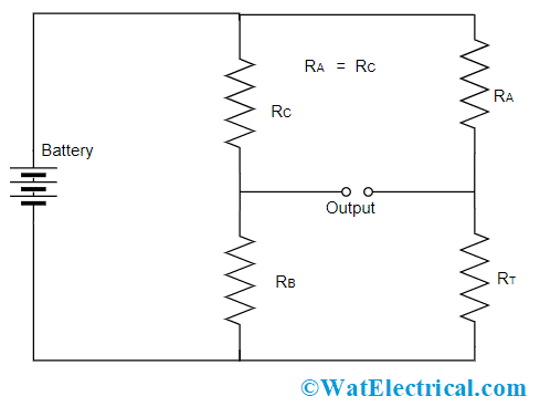
In order to measure temperature, the Wheatstone bridge is considered to be out of the balance condition. At this condition, a change in the voltage (ΔV) can be known corresponding to the thermistor’s resistance value. The below picture shows temperature measurement using a Wheatstone bridge with a thermistor.

Temperature Measurement Using Wheatstone Bridge
Selecting the correct value of resistors RB and RC eliminates the DC value from voltage change. Now, the below expression shows the relation between voltage and temperature where
ΔV = E [(RB/(RB+ RC)) – (RT/(RA+ RT))]
Let us consider that RA = RC, then
ΔV = E [(RB/(RB+ RA)) – (RT/(RA+ RT))]
RT = RA {[ERB – ΔV(RA + RB)]/[ERA – ΔV(RA + RB)]}
With this, the relation between T and RT is represented as below:
RT = R0 exp {β[1/T – 1/T0]}
So that
1/T = 1/T0 + 1/β ln {(RA/R0) ({[ERB – ΔV(RA + RB)]/[ERA – ΔV(RA + RB)]})}
Considering RA = RB = RC
1/T = 1/T0 + 1/β ln {(RB/R0) [E – 2ΔV]/[E + 2ΔV]}
So, with the above formula temperature can be measured using the Wheatstone bridge.
Even though T does not vary linearly with voltage, for minimal temperature change, this can be considered as a linear function and the errors can be eliminated.
Errors in Wheatstone Bridge
By calculating a value using Wheatstone bridge, the device may show few errors and those are explained as below:
- The device shows variation between specified value and actual value. This variation results in the error in measurement
- The device might show inaccurate measurements when a minimal sensitive galvanometer is considered
- In some cases, the bridge gets heated, and this might vary the resistance value and leads to mistakes in the calculation
- Errors in calculating minimal resistance values can also take place in the device because of thermal reasons
- Human errors can be one reason because persons can note down wrong readings while measuring
These are major errors in a Wheatstone bridge and these can be removed when proper galvanometer and resistors are used. Self-heating errors can be eliminated by noting the resistance value quickly and thermal errors can be reduced by reversing the switch connection in between the bridge and battery source.
Applications
The Wheatstone bridge applications are:
- Used to calculate changes in the incident light, so used in photoresistor devices
- Employed in measuring pressure and strain values
- Used along with thermistors to know temperature values
The Wheatstone bridge limitations are:
- The device shows inaccurate readings in an unbalanced state
- It can be able to measure resistance only to some extent of megaohms
Please refer to this link for Wheatstone Bridge MCQs.
1). What is the null point in the meter bridge?
The meter bridge has a slide wire which is of length one meter and a consistent cross-sectional area. When the jockey moves across the wire, at the balanced condition it shows ‘0’ deflection and this is termed as a null pointer.
2). What is the use of a wheat stone bridge?
The prominent usage of the Wheatstone bridge is in measuring unknown resistance and also to calculate other factors like strain and temperature.
3). What is the condition for the wheat stone bridge?
The condition for a Wheatstone bridge to be in a balanced condition is there is no current flow across the galvanometer.
4). What is the difference between the ohmmeter and Wheatstone bridge?
In Ohmmeter, the preciseness is constrained by the device’s internal resistance whereas in the Wheatstone bridge there is a constraint on accuracy and precise measurements can be known.
5). What is the advantage of the Wheatstone bridge over the ohmmeter?
When compared with Ohmmeter, the Wheatstone bridge has the ability to measure even very minute variations.
6). What is connected between the two ends of a Wheatstone bridge?
In between the two terminals of the Wheatstone bridge, a battery is connected and in between other pairs of terminals, a galvanometer is connected.
7). How to calculate resistance in the Wheatstone bridge?
Initially, connect the series resistances and create an ideal circuit and there has to be no current flow through the central resistor. Then, using the formula R1=1R1+1R2 (in parallel condition).
Know more about Electric Circuit MCQs, Schering Bridge MCQs.
So, this article has provided a clear analysis of the Wheatstone bridge’s working, its circuit, construction, limitations, errors, and uses. Know, how the Wheatstone bridge is used as a light detector?