There are various kinds of electrical panels and instruments which are mounted on board that allows sailing of ship easily between two ports in a more efficient and easy manner. This requires arranged maintenance and assessments to stay away from any kind of breakdown at the time of sailing. So, for onboarding purposes, there exist various devices and to measure multiple electrical factors. One of the instruments is the PMMC instrument (Permanent Magnet Moving Coil). Now, this article explains PMMC construction, working principles, various errors that occur in the device and applications.
What is PMMC Instrument?
This is also called a galvanometer or D’arsonval meter. The devices that utilize permanent magnet for the development of the stationary magnetic field in between the moving coils is termed as PMMC instrument. This device functions on the principle that when a moving coil is located in the vicinity of a permanent magnet, then there will be torque exertion.
This is a simple device that stands as support for frequent maintenance of the electrical components or when very accurate measurements are needed.
Construction
In the PMMC instrument construction, the main components are permanent magnets and moving coil. This section explains in detail the construction of the PMMC device and its components.
Moving Coil
It has turns that are constructed by silk-coated copper wires. When there is current flow across the coil and placed in the magnetic field locality, it generates deflecting torque which causes the coil to move, and the pointer starts to deflect corresponding to coil movement.
The moving coil is mounted on a former which is rectangular in shape and made of aluminum. In order to produce higher levels of torque and weight efficacy, the l × b ratio is kept in the range of 1.3 to 1.5. The aluminum former is swiveled on jewel bearings which makes the moving coil sides to be at the gap between magnet poles. In general, coils present in the voltmeter and ammeter are wounded in metallic shielded frames and non-magnetic frames.
Magnetic Arrangement
This device comprises two magnets that have a high level of intensity and coercive force, or a huge U-shaped magnet is considered depending on the device design. Magnets with high coercive force can generate fields that are in the range of 0.1 to 1 Wb/m2. For the magnetic field to be uniform, and the added iron cylinder is used in between both the magnetic fields. This decreases the air reluctance and enhances the strength of the field.
Controlling Spring
Here, two springs are used which are constructed using phosphorus bronze, and these springs function as a controlling system for a permanent magnet. The location of these springs is on the jewel bearings where provide the required amount of controlling torque. The torque development is essential because of the suspension in the ribbon. The springs resist the deflection force, so the EMF of the moving coil comes in line with spring tension.
This positioning of springs allows the pointer to stay at a constant position after the initial deflection and also helps in offering lead current directions for the system.
Damping System
With the movement of the aluminum core, the development of damping torque takes place in the PMMC device, and this damping makes the pointer to be at a constant position after the first deflection so that exact measurements can be considered having no vacillations. As because of magnetic coil movement, eddy current will also be developed in the aluminum former.
This generates the damping torque that contradicts further coil movement so that the pointer deflection reduces gradually and at last stays at one constant position.
Scaling & Pointer
When there is coil movement in the PMMC device, the pointer starts to deflect, and the pointer deflection is directly proportionate to the current in the magnetic coil. This pointer is a thin instrument and has minimal weight which is constructed of aluminum, and it has a flat surface at one of the edges which makes it a knife-edge.
The location of the pointer is on the spindle so that it causes movement in the graduated scale. The scale gets to the balanced position because of the balancing weight that is connected to it. Also, there is a mirror placed below the graduated scale so that it prevents parallax error.
PMMC Instrument Working
The PMMC instrument working principle is analogous to the working of the motor which means the scenario of how a rotor in the motor develops torque in the stator magnetic field. So, in PMMC instrument rotor corresponds to moving coil and stator corresponds to field generated by permanent magnets. The PMMC device schematic picture is shown below:
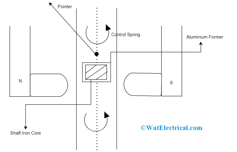
PMMC Instrument Construction
The magnetic coil starts to move and gets torque when the current that has to be measured is applied to the coil edges. This coil movement also allows a pointer to move as because the pointer is attached to it which even deflects the pointer. Here, the generated torque is termed deflecting torque and has a direct relation to coil dimensions and flux density. And the amount of torque developed equals the current which flows across the coil.
So, the pointer deflection value on the scale equals the amount of current magnitude which is being calculated which is very useful for measuring very exact DC measurements. The preciseness of the PMMC instrument lies in the range of 2 – 5% and the scale might be completely uniform.
Equations Involved in PMMC
Let us assume that below is the terminology used in the PMMC instrument
‘N’ represents the number of coil turns
‘L’ represents the coil’s vertical length measured in meters
‘d’ represents coil’s horizontal length measured in meters
‘I’ represents the amount of current flow per meter
‘β’ represents flux density measured in weber/m3
‘α’ represents the angle developed by the conductor corresponding to the magnetic field. As the field that exists in PMMC is radial, α = 900. As per Lorentz’s equation, the force on each coil is given by
F = N * B * l * L sinα
F = N * B * l * L sin900
F = N * B * l * L
So, the deflecting torque is
Dt = F * d
So that Dt = N * B * l * L* d
Whereas the coil’s area is a = L * d
Dt = G * I
The controlling torque is generated because of the spring controlling action so
Ct = Kϴ
Here, ‘ϴ’ represents deflection and
‘K’ represents spring constant
So that Ct = Dt
Kϴ = GI
Deflection = ϴ = GI/K
Error Causing Reasons in PMMC
The following section will explain on what are the different reasons that cause an error in PMMC?
- Magnets tend to lose their magnetic properties with respect to time and it is termed magnetic aging. Also, accelerated aging takes place because of exerting a high level of vibration and heat. Due to the reduction in magnetic strength, the deflection in the coil shows the impact on its readings.
- As the coil in the PMMC device is constructed of copper wires, the copper wires’ temperature coefficient will be 0.0040/C. With this, when temperature increases, the resistance increases thus showing variation in actual reading level.
- Aging in the PMMC instrument causes deterioration of spring tension which also reduces the deflection of the moving coil. The error generated because of spring contradicts with the magnetic aging error and in few cases, they both get canceled so that more difference in the final readings is decreased.
Advantages and Disadvantages
Here are the advantages of the PMMC instrument
- In PMMC instruments, the division of scaling is done accurately
- These devices consume minimal power for the entire functioning of the device
- As because of the increased torque-weight ratio, the devices exhibit high accuracy levels
- With the usage of multiple shunts & multipliers, a single PMMC instrument can measure different current and voltage ranges
- The damping because of eddy current is very efficient
The disadvantages of the PMMC instrument are:
- PMMC instruments are used only for measuring DC measurements
- The cost incurred for its construction is more
- Because of aging and heat, various errors show impact on the device readings
- Due to the springs aging, deflections get varied, and errors get introduced in the device
- PMMC device moving system is so delicate and it gets easily damaged if there is poor maintenance
Applications of PMMC Instrument
PMMC instruments are used in the constructions of:
- Ballistic galvanometer
- Fluxmeter
- AC type of galvanometer
- Also employed in ammeters
- Used in voltmeters
Why PMMC instruments are not used for AC measurements?
As discussed in the above sections that in PMMC devices the deflection torque has a direct relation with the current which corresponds that torque rotation will vary for every 1800 of A.C. This takes place because of switching in magnetic polarity of the electromagnet.
As because of inverse deflection for each 1800 of A.C, the net torque developed equals ‘0’. So, PMMC instruments are not employed for measuring A.C currents.
Please refer to this link to know more about Moving Iron Instrument MCQs.
So, this is all about the PMMC instrument. This article has provided entire and detailed knowledge on PMMC working, construction, equations involved, benefits, drawbacks, and uses of it. Also, know how the PMMC instrument is used as an ammeter?