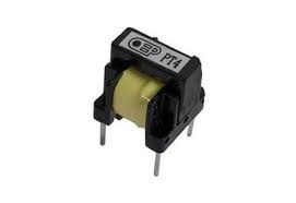
A pulse transformer is also known as trigger transformer, gate drive transformer, gate transformer, signal transformer (or) wideband transformer in some applications, a. The main function of this transformer is to transmit voltage pulses between windings and the load. These transformers are used for galvanic isolation (signal transmission), low-power control circuits, & the major components used in high-power SMPS. By using this transformer, amplitude in the voltage pulse can be changed; the polarity of the pulse can be inverted, coupling different stages in the pulse amplifier and an isolation transformer.
What is a Pulse Transformer?
Definition: A transformer that is enhanced to produce electrical pulses with high velocity, as well as stable amplitude, is known as a pulse transformer. These are regularly employed while transmitting digital information as well as in transistors, mainly in gate drive circuits.
The perfect transformer must have galvanic isolation and distributed capacitance. For the circuit protection, capacitance with low coupling is also vital to defend the circuit.

pulse-transformer
Signal types of pulse transformers are range from complementing logic drives to transmission lines. These transformers work with lesser power thresholds. Several such transformers serve like wideband transformers. For digital data transmission types of transformers, they are enhanced to reduce signal distortions.
The signal conformity & frequency range can be determined through exterior features such as inter-winding capacitance, each winding individual capacitance and also resistance.
Negative effects of these features will result in droop, overshoot, backswing & fall time and deterred rise. So pulse transformers are designed based on inductance, operating frequency, power grades, voltage ratings, size, frequency range, resistance, and winding capacitance.
Types of Pulse Transformers
These transformers are classified into two types like the following
- Power pulse transformer
- Signal pulse transformer
1). Power Pulse Transformer
These transformers change voltages from power-level (one level/phase configuration) to another. The configurations of these transformers are accessible in either 1-phase or 3-phase and vary with how the winding is connected.
2). Signal Pulse Transformer
These transformers are one kind of pulse transformers, uses electromagnetic induction for transmitting one circuit’s information to another. They are regularly used to raise or reduce the voltage in a power transformer from one surface to the other. By using signal transformers, the no. of windings turn ratio decides to modify in voltage.
These transformers contain low-loss cores, designed to run at high frequencies. Parasitic elements like winding capacitance & leakage inductance can be reduced by designing the winding configuration so that coupling can be enhanced.
Performance Specifications
These transformers mainly include performance specifications like repetition rate, duty cycle, pulse width, range, I/O voltage, current, frequency & physical dimensions like length (L), width (W) and height (H).
The frequency of pulse repetition rate is the standard no. of pulses for each unit of time in a particular period. Pulse width is the period between the primary and final instances that immediate amplitude achieves a particular fraction of peak pulse amplitude.
Construction
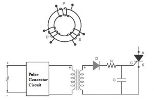
The construction of a toroidal shaped transformer is shown below. The main objective of this transformer is to produce a pulse for semiconductor devices as well as give electrical isolation.

pulse-transformer-construction
The above figure shows the transformer in a toroidal shape. It includes two windings namely primary and secondary. Every winding includes an equal number of revolves so any winding from these can work like primary otherwise secondary.
The pulse to SCR can be given through 1:1 otherwise 1:1:1 pulse transformer and pulse to the continuous SCR can be given through the 3-winding transformer. In the above figure, the series resistor (R) is to stop the holding current of the silicon controlled rectifier. The main function of the diode in the circuit is to avoid gate current which is reversing. The pulse transformer of 1:1:1 is mainly used to produce a pulse for continuous SCR.
This transformer design is discussed in the above. Once the design is done, the transformer efficiency must be high. The primary winding’s inductance in the transformer must be high for decreasing magnetizing current. The DC supplies through the main winding of the transformer to avoid saturation of the core. Insulation must be there among windings to defend winding from saturation. Fixed coupling between two windings should be required. The stray signal gives lane during interphase capacitance on a high frequency.
Pulse Transformer Advantages & Disadvantages
The advantages of this transformer include the following.
- Small size
- Less cost
- Operates at high frequency
- Isolation voltage is high
The disadvantages of this transformer include the following.
- At low frequency, both the primary and secondary waveforms are different from each other.
- Saturation current of the core can be reduced because of DC through the primary winding.
Pulse Transformer Uses
- The uses of this transformer include the following.
- Signal pulse-transformers are used in telecommunication, digital circuits
- Power pulse-transformers are used to isolate power circuits from the control circuit.
- High voltage pulse-transformers are used in radar application & pulsed power applications.
- Power electronics
- Radars
- Digital electronics
- Communication
Thus this is all about pulse transformer, and these are used for computer digitization, devices measuring as well as pulse communication. Some kinds of transformers are employed within the electrical power supply industry to make a frequent boundary among low voltage control of circuitry & high voltage gates in power semiconductors. Here is a question for you, what are the Pulse transformer operating principles?