The term ‘Polarity’ can be defined as when an entity has two different & reverse poles that can either repel or attract each other. The term ‘polarity’ is used in different fields like electricity, electronic signaling, chemistry, and magnetism to explain the flow of electrons. Similarly, reverse polarity is quite opposite to it which means it is a condition where an outlet’s electrical wires are connected simply in reverse. Whenever the two poles are simply connected through a wire then electrons will flow from the negative to the positive pole which is known as electric current. Whenever the current flows between two poles or points, if one of the poles has more electrons than the other pole, it is negative polarity whereas the pole with fewer electrons is known as positive polarity. This article provides a brief information on reverse polarity.
What is Reverse Polarity?
Reverse polarity can be defined as; an electrical condition where both the terminals of a DC system are connected mistakenly in reverse. Generally in the standard configuration of polarity, the positive terminal (+) is connected directly to the positive side whereas the negative terminal is connected to the negative side of a power source. But, whenever this polarity happens, then it leads to hazards and potential issues. The reverse polarity in a DC circuit means, changing the positive & negative connections so that the flow of current will be in the reverse direction. The reverse polarity in the AC circuit changes the AC wave direction.
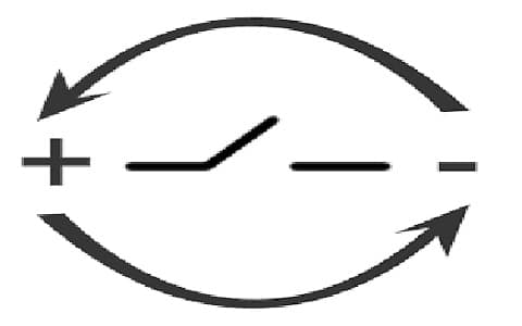
Reverse Polarity
Is Reverse Polarity Dangerous?
Reverse polarity in a circuit can affect or damage the electrical circuit or devices, thus it is very significant to understand the effects before trying to do so. This polarity has many effects based on the involved equipment or device. For instance, reversing a motor’s polarity could cause it to revolve in the reverse direction, whereas reversing a magnet’s polarity could cause it to keep away instead of attracting other magnets.
If you notice that outlets of your home wall have this polarity, then correcting the trouble is difficult, but, you have to be cautious otherwise you can get shocked (or) electrocuted. Before checking the electrical wiring, you must turn off your electricity supply. Generally, positive wires are normally in red (or) black color that must be connected to the brass terminal whereas Neutral wires are normally in gray or white color, they must be connected to the chrome terminal. If the electrical wires are not connected correctly, then it is known as reversed polarity so it can cause electrical shock when anyone touches the outlet or device & even harm to the device itself.
Reverse Polarity Protection Circuit Diagram
Reverse polarity protection is a circuit, used to ensure that the system or device is not damaged if the polarity of the power supply is reversed. This circuit cuts off power simply to the responsive electronic circuits within the transducer/transmitter.
The reverse polarity protection circuit with P-channel MOSFET is shown below. This method is more reliable as compared to others due to high current ability & low voltage drop. The required components to make this circuit mainly include; FQP47P06 P-Channel MOSFET, 100k resistor, 9.1V Zener Diode, and connecting wires. Connect the circuit as per the circuit shown below.
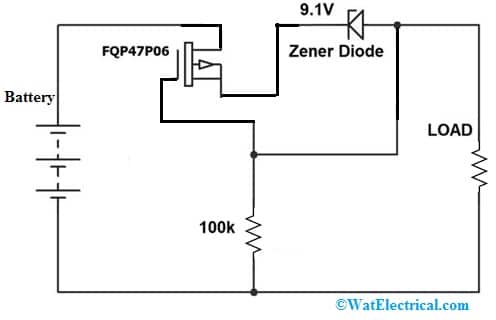
Reverse Polarity Protection Circuit Diagram
If the voltage supply is below the Vgs (gate-to-source voltage) of the MOSFET then you need only the MOSFET without a resistor or diode. So you have to connect just the MOSFET’s gate terminal to the GND. If the voltage supply is above the Vgs then you have to drop the voltage in between the gate & source terminals.
Working
In the above circuit, whenever the battery is connected properly it makes the MOSFET switch ON by allowing the flow of current throughout it. This transistor will be switched ON due to the voltage supply between the gate & source terminal is negative. We know that the P-Channel type MOSFET will only turn on when the voltage at the gate terminal is negative. To find the voltage between gate & source Vgs = (Vg – Vs). If the battery’s terminals are connected in reverse polarity then the MOSFET will switched OFF and the circuit will be protected
When the MOSFET is turned ON the resistance between two terminals like the drain & source is nearly small. For FQP47P06 MOSFET, the maximum static drain-source On-resistance is 0.026Ω. Thus, the power loss within the circuit can be calculated as; power loss = I2R.
When the flow of current throughout the MOSFET is 1A then power loss can be calculated as;
Power Loss => I2R = (1A)2*0.026Ω => 0.026W
Thus, the power loss is about below more times than the circuit with a single diode. So protection circuit using P-Channel MOSFET is better as compared to other methods but it is costlier and it makes the protection circuit very much efficient & safer. In this circuit, a resistor & zener diode are used for protection from increasing gate to source voltage. So by using the Zener diode & resistor, we can clamp the voltage from gate to source to a highest of negative 9.1V, thus the MOSFET remains secure.
How to Fix Reverse Polarity?
This polarity can be fixed very easily by switching the electrical wires to their equivalent sides. Fixing this polarity for an outlet is quite simple. So the following steps are very helpful in fixing this:
- Turn off the power to the outlet/room.
- Need to take away the wrap of the outlet & outlet from the wall.
- Take out the red or black & white color wires from the outlet.
- Connect the red, black & white color wires to the exact side.
- Ensure these wires are protected properly & make good contact.
- Situate the outlet on the wall with the wrap on.
- Turn on the power back.
- Need to test the outlet using an outlet tester to make sure it is working correctly.
Reverse Polarity Relay
When reverse polarity is applied to a solid-state relay coil it damages the coil & the relay itself. Generally, the relay coil will not work correctly & may not shut the contacts. The relay coil may break down/damage in some cases and it damages the relay potentially as well as any connected devices. It is significant to verify the polarity & specifications of a relay always before providing power to the relay coil.
Reverse Polarity Switch
The reverse polarity of the switch can interrupt the intended electrical current flow & impact negatively on the performance & security of the devices connected.
Reverse Polarity Welding
The reverse polarity in welding is a condition where the electrode is connected to the positive & the work is connected to the negative. The flow of electrons from negative (-ve) to positive (+ve) thus, a large quantity of heat emerges at the electrode typically 2/3rd of the entire heat. This can be done for the thinner plates welding. Penetration of weld is less because of the low amount of accessible heat toward the work.
How does polarity Get Reversed?
The polarity gets reversed whenever the hot & neutral wires are connected in reverse.
Will GFCI work with Reverse Polarity?
Yes, it works with reverse polarity. GFCI compares the current flowing in/out of one slot through the other slot. When it is AC, which manner you connect the connecting wires doesn’t matter but a GFCI tester most likely wouldn’t work & it would specify that the GFCI was not good as it wouldn’t trip.
What is a Reverse Polarity Battery?
The reverse polarity of the battery is the case whenever the source/load cables are incorrectly connected then a current may flow within the circuit & cause some damage & serious injuries to the equipment.
What Causes Reverse Polarity?
The reverse polarity can cause fire and damage components or wires. This reverse polarity can also result in very serious electrical shock.
What happens if the Neutral Wire is not Connected?
If the neutral wire is not connected or broken then it causes an influx of voltage that can harm electronic equipment. If there are difficulties by the neutral line, then electricity may be supplied throughout different lanes to get away.
Common Causes of Reverse Polarity
The common reverse polarity causes are discussed below.
Wrong Connection of Battery
The wrong connection of the battery leads to reverse polarity and it potentially damages the electronic devices that are connected.
Misplacement of Component
When components are connected incorrectly on a printed circuit board can accidentally cause a condition of reverse polarity.
Incompatible Power Adapters
A reverse polarity condition can occur with an AC or DC wall adapter through an incorrect polarity connector. This can cause harm to the circuit/device.
Errors of Wiring
When wires are connected wrongly on a PCB then it can cause reverse polarity, mainly when connections of power are involved.
Errors of User
Improper connection or handling of electronic devices with consumers can also lead to the issues of reverse polarity.
Symptoms & Consequences
Some of the reverse polarity symptoms & consequences mainly include the following.
- When an electronic device experiences reverse polarity it exhibits erratic performance, complete failure, or intermittent operation.
- Electronic components with reverse polarity can overheat and it can damage or affect that part completely.
- Reverse polarity in a PCB can cause short circuits, blow fuses potentially & damage other components.
- For reverse polarity, an extended exposure can damage sensitive components permanently like transistors & integrated circuits.
- Reverse polarity in extreme cases can lead to dangerous situations like fires, explosions, and electrical shocks mainly when batteries or high-power devices are involved.
Advantages & Disadvantages
Reverse polarity advantages include the following.
- Reverse polarity is beneficial in overhead welding because the workpiece within in reverse polarity is made negative thus; less quantity of metal is dissolved
- Aluminum & magnesium will work better by reverse polarity due to their low melting point.
- Reverse polarity generates a more penetrating arc as compared to straight polarity. It is suitable for welding thick metal pieces because it gives less distortion & a very strong weld.
- This polarity is used whenever welding with layered electrodes to give greater stability & prevent the electrode from dissolving.
Reverse polarity disadvantages include the following.
- The main drawback of this polarity is that it gives a less stable arc as compared to straight polarity. So this can make it harder to manage the weld & produce a worthy result.
- This polarity generates more heat as compared to straight polarity due to semiconductor breakdown, so it is a problem whenever materials are responsive to heat or welding thin materials.
- This polarity is very hazardous because it causes harm to anyone or the risk of death.
- This polarity can destroy so many inverters and cause fire outbreaks, etc.
- This polarity harms electronic components like transistors, diodes, etc.
- This type of polarity can cause damage if it goes above the breakdown voltage of responsive components.
Thus, this is an overview of reverse polarity, working, advantages, disadvantages, and its applications. Reverse polarity is changing the flow of current direction within a circuit. In an AC circuit, reverse polarity can change the AC wave direction whereas in a DC circuit, the current supplies in the reverse direction. This polarity has various effects based on the equipment/device involved. The reverse polarity in some cases can cause damage to the electronic circuit or devices connected. The protection of reverse polarity is necessary for a device that uses DC power, mainly when there is a risk of wrongly connecting an electrical battery. Thus it is significant to understand the effects before trying to do so. Here is a question for you, what is polarity?