The evolution of the Rogowski coil happened with simple solenoids and these coils were in usage from the period 1912. The initial usage of the coil was very limited because of its minimal output voltage which was not enough to lead the measuring equipment. Whereas with the enhancement measurement sensitivity, the implementation of coil enhanced and those were in use in many applications across many domains. A tool that operates similar to the coil as defined by person Arthur Prince Chattock in Bristal University in the year 1887. He utilized this device to know corresponding magnetic fields instead of currents. The final descriptive definition of this coil was given by Walter Rogowski and Steinhaus in the year 1912.
What is Rogowski Coil?
A Rogowski coil is termed as the electrical instrument which is used for the measurement of AC or high speed of current pulses. In few cases, the device is included with a wire coil of helical shape having lead at one edge that crosses from the center of the coil to the other edge so that both the edges are at coil’s one edge only. This style is sometimes called as counter wound type of Rogowski. These coils are also termed as air-cored coils. This is the basic Rogowski coil theory.
Design and Circuit of Rogowski Coil
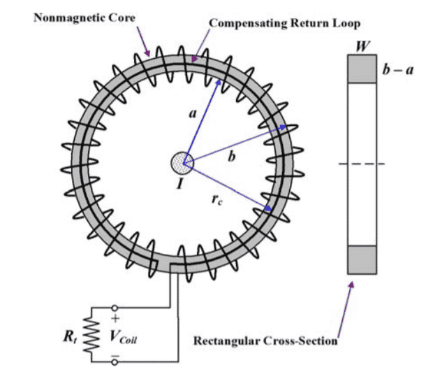
The Rogowski coil design is shown below:
Here, the coil is constructed using helical winding which is placed on the toroidal solid coil where is made of a non-magnetic substance. The diagram depicts that the compensating return loop of the winding consolidates with the total circumference length. This consolidation generates an undesirable one-turn circle normal to the coil’s axis. The equivalent Rogowski coil circuit for the construction is shown as follows:

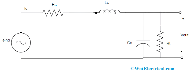
Equivalent Circuit of Rogowski Coil
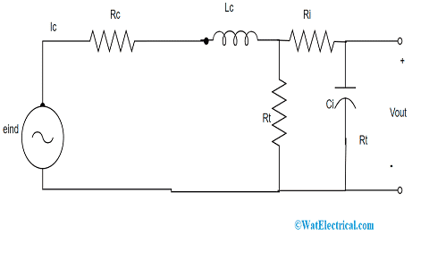
It consists of self and mutual inductance of Lc and Mc, the resistance of Rc, self and terminal capacitances of Cc and Rt and a voltage source, and the entire circuit functions as a coupling circuit. As per the principle of Faraday’s law, eind has direct proportion to (dI/dt) for current compatibility and induced voltage signals, the terminals of the coil are connected to an integrator. It was stated that a passive kind of integrator circuit holds more competence when compared with an active integrator. When the above equivalent circuit, the coil is replaced by a passive integrator circuit, then the circuit is shown as follows:

Equivalent Circuit With Passive Integrator
Working Principle
The working principle of Rogowski coil is dependent on faraday’s law theory. The functionality of this coil is the same as the AC type of current transformers. In CT devices the induction of voltage that takes place in the secondary coil is directly proportional to the amount of current that flows across the conductor. The main variation which is in between AC CTs and the coil lies in their core section. In the Rogowski coil, the air-core acts as the core section, and in CTs a steel core is utilized.
When there is current flow across the conductor, this generates a magnetic field. As because of magnetic field intersection, there develops a voltage induction in between the coil terminals.
The induced voltage magnitude is directly proportional to the amount of current that flows across the conductor. These coils are close pathed coils. In general, the output of the coil is received from the integrator circuit. Because of this, the coil’s voltage is combined to provide the output level of voltage which is directly proportional to the input current signal.
Based on this working principle, the Rogowski coil formula is given by
v = L (dI/dt)
Here ‘L’ corresponds to the coil’s inductance and the inductance is given by
L = µ0AN/I
In the inductance formula, ‘A’ represents coil’s cross-sectional area = πr2
‘l’ corresponds to coil length = 2πr
‘N’ corresponds to coil turns
‘µ0’ corresponds to the magnetic permeability of air = 2π × 10-7 A/m
In order to gain output voltage that is proportional to the current of the conductor, there has to be an integrator circuit that has a connection with the coil edges. So, the output voltage is then given by
V0 = ʃL(dI/dt)
= (µ0AN/I)I + C
In the design, ‘C’ is made as null which is then given by
V0 = (µ0AN/I) I
Rogowski Coil vs Hall Effect
As there are multiple approaches to current sensing, this article shows how to sense current through the Rogowski coil and hall effect and what are their differences.
| Rogowski Coil | Hall Effect |
| Delivers voltage which is proportional to the rate of change in alternating current | Delivers voltage which is proportional to the rate of change in either AC or DC magnetic field |
| These are mainly used for retrofitting and high-current purposes | Employed mainly for open-loop and closed-loop applications |
| It has a minimal current range | It has a medium current range |
| The temperature drift of the coil is high | The temperature drift of the coil is medium |
| It has inherent isolation | It has inherent isolation |
| The accuracy of the Rogowski coil is very less | The accuracy of the Hall effect is very medium |
Accuracy
The Rogowski coil accuracy is dependent on the current probes those range in between +1% to +2% of full scale. Apart from the measuring tools and approaches, accuracy is also based on few other factors like winding capability, the cross-sectional area of the coil, and density of all the turns.
Rogowski Coil Testing
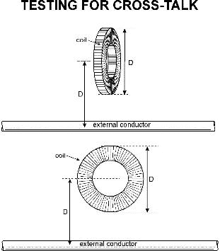
Rogowski coils are generally tested to analyze the coil’s sensitivity towards cross-talk or collect from the current-carrying conductors where it does not stand the coil from external magnetic resources. This kind of testing is achieved by making a conductor be close to the current-carrying conductor and then evaluating the coil’s output with the output value which is obtained with the coil that encircles the conductor.
The amount of rejection is represented as a percentage. Mostly, when a uniform winding is considered, then the pick-up should be null. In certain, there will be minimal winding issues and the pick-up ratio is considered as a quality check.
This is the picture that shows the positioning of the conductor. The coil is rotated in all directions to know in which direction it collects the maximum level of pick-up. In the case of flexible coils, it is less than 1%.
Advantages and Disadvantages
The advantages of Rogowski coil are:
- The response of the coil towards quick varying currents is more
- The temperature compensation of the coil is not complicated
- The coil is available in both rigid and flexible types
- The size of the coil is less when compared with the general transformer size
The disadvantages of Rogowski coil are:
- An additional integrator circuit is needed which increases the coil’s circuitry
- It has no ability to measure DC current
Applications of Rogowski Coil
The applications are:
Rogowski coils are mainly implemented for current scrutinizing in accuracy welding systems, arc melting boilers, or electromagnetic catapults. They are even applicable in short-circuit analysis of electric generators and utilized as sensors in the protection system. The other domain of application is the measurement of harmonic current content, because of their increased linearity.
Know more about Electromagnetic Field Theory MCQs.
So, this is all the concept of the Rogowski coil. This article showed a description of Rogowski coil working, theory, testing, accuracy, benefits, and applications. Know how Rogowski coil is used for the measurement of AC of various signals?

