The development of the electrical and electronics industry seems to be continually progressing with the invention of various electronic devices. The one device that has to be probably discussed is a Transformer. There is a wide range of applications through a transformer and just not with a single type of transformer, scientists have invented various kinds and each one has its own applications and advantages, either in commercial or real-life scenarios. So, let’s go have an overview of what a transformer is and what are the various types of transformers?
What is a Transformer?
So, basically, a transformer is defined as a static device that holds the ability to transform one circuit’s electrical energy to others through the means of electromagnetic induction. It can be either implemented to maximize (stepping up) or minimize (stepping down) the levels of voltage between the circuits. One might be in the thought of how there can happen the transform of energy. So, it is through the principle of mutual induction where the flux which is stimulated in the initial winding gets associated with the secondary winding. Only by increasing or decreasing the power and voltage levels, transfer of energy take place while allowing the frequency term to be constant.
Types of Transformers
Electrical power systems will implement various types of transformers based on transmission, power generation, distribution, power usage and also on the organization requirements. Different types of transformers can be classified based on the level of voltages, a core medium that is used, winding activities, installation location, and many other aspects. In general, we shall go with the discussion on the below types of transformers.
Auto Transformer
It is a kind of transformer that has only one winding rolled on the laminated core part. This is the same as that of a two-winding kind of transformer but varies in the approach that both the windings are interconnected. Some part of the winding section is shared between the two windings. In the case of load, some part of the load current is acquired from the supply and the rest is acquired from that of transformer activity. It functions in the same way as a voltage regulator.
Circuit Diagram
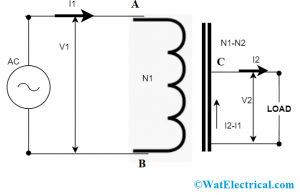
In a general transformer, both the windings are insulated electrically while these are magnetically connected and in auto-transformer, both the windings are connected both electrically and magnetically.
Here, AB acts as the primary winding and CB as the secondary winding. The voltage is applied across the terminals AB and the CB acts as the load current. The tapping can be either variable or fixed. So when the voltage is applied across AB, emf is generated in the winding at AB and a part of this emf is passed on to the secondary winding. In the diagram,
auto-transformer
Here, V1 and V2 are the primary and secondary voltages
I1 and I2 are primary and load currents and
N1, N2 is the no. of winding turns across AB and CB
Here, the transformation ratio is represented as K
and K = V2/V1 = N2/N1 = V1/V2
The implementation of autotransformer shows the benefits of less implementation cost, enhanced regulation, and negligible losses. Few of the applications are
- Utilized as a voltage regulator
- Implemented in audio devices and railway
- Provides a boost to the distribution cables to manage the voltage loss
Power Transformer
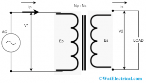
To transmit increased voltages, power transformers are mostly utilized. Power transformers are available in various ratings such as 33 KV, 400 KV, 66 KV, 110 KV, and 200 KV. Most of these are rated above the range of 200 MVA. And generally implemented at transmission substances and at power generation stations.
Power transformers are absolutely effective to generate 100% output but are bigger in size. Uncomplete loading of this results in core losses whereas the copper loss is dependent on the distribution network’s load cycle. There will be minimal load fluctuations when it is coupled with the transmission system as these are not directly linked to the customer. But, when there is a direct connection, load fluctuations start to increase.
power-transformer
As the power transformers are loaded for the whole day at transmission stations, there will copper and core losses. These are economical when operated at minimal voltages. When there is an increase in voltage, the current is decreased, so there will be a reduction in I2R losses, and the voltage control is enhanced automatically.
So, efficiency is denoted as
V1/V2 = Is/Ip
The power transformer shows the benefits of
- Minimal magnetic losses
- Streamlined installation procedure
- Small size
Isolating Transformer
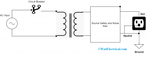
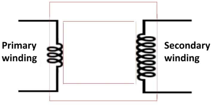
Isolation in the name itself indicates that separation. In general, a transformer is a device where the primary and secondary windings are connected to the main and load circuits. Whereas, in the isolation transformer both the windings are isolated (separated) from each other. Isolating transformers are mostly implemented when the oscilloscope calculates signals in the circuit that is not galvanically separated from the circuit.
The foremost benefit of these are; safe and people can be completely away from electrical shocks. Fundamentally, the secondary side of it is grounded. Even at the time of breakdowns, these devices can generate some voltage, because one of the sides is under voltage and can raise beeping sounds.
isolation-transformer
As these are constructed with electrostatic shields, they hold an enhanced ability to suppress noises and other interactions. A perfectly designed isolation transformer eliminates ground loops., where these develop additional current flow. And, this is one of the causes of interferences.
Pulse Transformer
It is an optimized transformer used for the transmission of electrical pulses those have extreme fall and rise times maintaining comparatively constant amplitude. A trigger transformer is a kind of pulse transformer and implemented to instigate some sort of activity. Based on the variations of the factors like operating frequency, size, inductance, voltages, power ratings, impedance, and winding ability, the design of the transformer varies. Using the correct winding configurations, there reduces the scope of leakage inductance, interference, and winding capacitance.
pulse-transformer
The design of the pulse transformer varies as per the below conditions:
- To reduce the pulse distortion, it has to be designed with minimal values of capacitance, leakage inductance, and enhanced open-circuit inductance.
- Mostly, low coupling capacitances have to be used to manage the whole circuit from the load transients. Thus, because high insulations and breakdown voltages are also necessary.
A few of the applications of pulse transformers are in-camera flash switches, digital communication, and logical devices, matching transmission lines with logic drivers. Also implemented in the electric power transmission domain to interface minimal voltage circuit board with that of increased voltage gates of power type of semiconductors.
Grounding or Earthing Transformer
This is used to show a specific path for the ungrounded structure or when the structure neutral does not exist, as because of this it is connected in the delta approach. Through this, a minimal impedance for the neutral and even regulates the transient extended voltage when there occurs any ground issue. Earthing transformers are connected as in the following approaches:
- Delta-star
- Zigzag
Delta-Star Grounding
Here, the delta way is closed so as to show a way for the zero-sequence current. The star winding needs to be of similar voltage rating because the circuit needs to be grounded, while the delta voltage rating might be at any basic voltage level.
grounding-transformer
So, choosing of grounding approach is based on the below conditions:
- Internal transient voltage
- Voltage in dip-in-line in case of faulty conditions
- Voltage levels and the system type
Resonant Transformers
In the case of high voltage generation, single-phase transformers are not effective because of complicated construction, expensive, and many losses. To surmount these disadvantages, cascading transformers are invented, but they also have certain limitations and disadvantages. In the scope of this, resonant transformers came into launch.
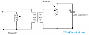
resonant-transformer
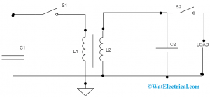
Resonant transformers are used to generate high voltages that work on resonance phenomenon where XL = Xc. In resonant scenarios, the current flow through the test item is more and it can be limited by the implementation of resistance in the circuit. The circuit diagram of these transformers is included with a leakage resistance of the windings, resistance winding, both the shunt capacitance and magnetizing reactance that is throughout the end terminals because of the high voltage terminal.
At the condition of power frequency, series resonance can be obtained where it is represented as
(L1 + L2) = 1/wC
Across the capacitance, the magnitude can be calculated as
Vc = [-jV Xc/ { r + j(Xl – Xc)}] = V/(wCR), where R represents entire circuit series resistance.
The factor 1/(wCR) is considered as the circuit’s Q factor. So, the input voltage and kVA that are necessary for the excitation gets diminished by 1/Q. And also, the circuit’s secondary power factor is 1.
A few of the benefits of implementing resonant transformer are:
- These are implemented when there is the necessity for high current and voltages, and in the scenario of intense high voltages, cascading can also be achieved in a simple manner.
- A pure and exact sinusoidal waveform can be generated
- Just a small amount of power is needed
- Shows complete protection
Audio Transformer
Audio transformers operate at the frequency range of 20 Hz – 20 kHz and they are mostly implemented in the audio amplifier systems. With the isolation property, these types of transformers develop isolation between the end speakers with the support of the transformer’s internal existing amplifier system. In that scenario, the proportion of both the windings has to be 1:1. Owing to this, the device will not change its current or voltage levels, it just develops isolation between the output speaker and input amplifiers.
Although there is no connection between the two windings, this transformer holds the ability to provide bidirectional support, and in this condition signal loss happens in one way and signal gain in the opposite way. This transformer makes use of an impedance balancing approach. The impedance ratio of the audio transformer can be calculated as
Zprimary /Zsecondary=(Np/Ns)2 = (Vprimary/Vsecondary)2
Where Zprimary corresponds to the primary impedance
Zsecondary = secondary impedance
Even there exist various kinds of audio transformers such as impedance matching transformer, a step-up audio transformer having extensive frequency range, that is within the audible frequency, a step-down audio transformer having extensive frequency range that is within the audible frequency.
Oil Cooled Transformer
Transformer cooling is the procedure of indulgence of heat that is generated in the transformer to the atmosphere. The losses that happen in the transformer are transformed into heat that enhances both core and windings temperature. So as to dissolve the generated heat, the cooling process should be done. And this cooling will be done in various methods such as oil, air, air-blast and many.
In the oil-cooled transformers, heat is transferred to the oil which exists at the surrounding of core and windings and it is then performed to the transformer tank walls. In the end, the heat is transferred to the surrounding air through the process of radiation and convection.
When compared with air coolants, the benefits of oil coolants are
- It delivers improved conduction than that of air
- Elevated coefficient of conduction that delivers the natural kind of oil circulation.
Classification of Transformers
Transformers work on the principle of mutual induction. It steps up or down the input voltage based on a number of windings. Here, the classification of transformers, along with their principle of operation has been explained. There are many methods based on which the transformers are classified. The methods and the principle of classifications have been given as follows.
Based on Function
Based on function, the transformers are classified as step up or step down transformers.
Step-up Transformers
In this category, the transformers amplify the input voltage based upon the number of turns.
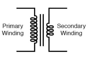
Step Up Transformer
As shown in the figure, let E1 be the primary induced voltage, E2 be the secondary induced emf. N1 be the primary turns and N2 be the secondary turns. From the fundamentals of the transformer, we know that E1/E2 = N1/N2. The ratio N1/N2 is also called a turns ratio of the transformer. For a step-up transformer, N2 is greater than N1. From the ratio, it can be easily obtained that, for that case, E2 is greater than E1. Hence is acting as a step-up transformer. This means that the secondary induced emf is greater than the primarily induced emf. Such transformers are used on the generation side, where is generated voltage is stepped, and transmitted through long transmission lines to reduce the losses and improve efficiency.
Step down Transformers
In this category, the transformers reduce the input voltage based on the number of turns.
Step Down Transformer
As shown in the figure, for this transformer, the turns on the secondary side i.e. N2 are less than turns on the primary side N1. From the fundamentals of transformers, it can be easily seen that E2 is greater than E1. This means that the secondary voltage is less than the primary voltage. Such transformers are used on the distribution side. Which is on the utility side. High voltage from the transmission side enters the step-down transformers, its magnitude is reduced and fed to the utility. The utility may be residential homes or industries.
Based on Core Construction
Transformers are also classified based on the core arrangement. Based on this they are classified as
Core type Transformers
As shown in the above figure, in a core-type transformer, the core is surrounded by windings. In the two limbs of the transformer, as shown the winding is wound. The limbs have equal dimensions.
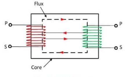
Core type Transformer
The core type is also called a series magnetic circuit as the same amount of flux flows through both the windings. This name is given based on the equivalent current circuit. Such transformers are used for high kVA ratings since they can withstand more currents than voltage due to their series property.
Shell Type Transformers
As shown in the below figure, in a shell-type transformer, the windings are surrounded by the core. The windings are wound around the central limb. The dimension of the central limb is around two times the outer limb. But in core type, all limb dimensions are the same. The shell type is also called a parallel magnetic circuit. Since the flux gets divided into the two parts of the transformer.
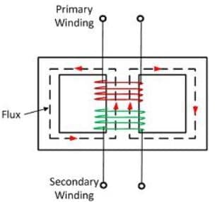
Shell type transformers
This is again equivalent to electrical equivalent. Such transformers are used for low kVA ratings since they can withstand fewer currents. It is be noted that the transformer rating is in kVA, not kW. This means that the transformer rating is an independent power factor and depends on temperature rise. The temperature rise is again dependent on currents. That is the reason, the rating of transformers is dependent on currents.
Based on the Nature of Supply
Based on the nature of supply, the transformers can be classified as single-phase transformers and three-phase transformers.
Single-phase Transformer
In this type, the input voltage to the transformer is a single-phase supply. Such a transformer can be of step up or step down. Generally, single-phase transformers have fewer applications, and most are found on the utility side. The ratings of the single-phase transformer may go up to 5 MVA, 230V. Such transformers can be also of core type or shell type.
Three-phase Transformers
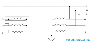
Three-phase transformers find huge applications over the power systems.
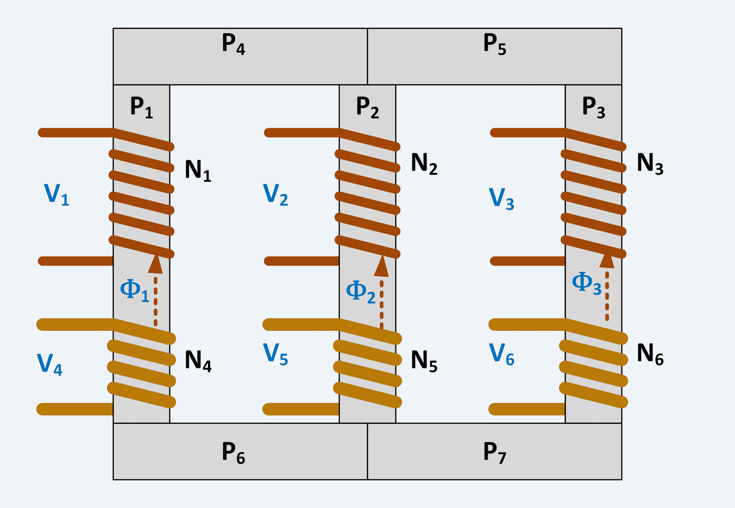
Three-phase transformers
As shown in the figure, it consists of three limbs, supplied with each phase of the three-phase. They can be also core type or shell type. In the figure, a core type three-phase transformer is shown. Their ratings go up to 500-1000 MVA. Or even more, based on the applications. One important criterion of the three-phase transformer is its configuration. Since we know that, the three-phase connection is given in star or delta. So based on that, the configuration of a three-phase transformer may be star-star, star-delta, delta-star, or delta-delta.
The first word implies primary connection and the second word implies secondary. When we say star-delta, it means that primary is connected in star, and secondary is connected in delta. Each configuration has its own phase difference and even commercial name like Dd12 etc. The configuration of the three-phase transformer is one important criterion in nameplate details.
Based on the Use
Based on use, the transformers are classified as
Power Transformers
This classification of transformers is found at the generating side of power systems. Such transformers are of high ratings. They step up the voltage that is generated by the three-phase alternators. They are of high ratings i.e. up to 1000 MVA. To reduce the transmission losses the generated voltage is stepped up from 11 kV to 450 kV. And transmitted up to long distances. These transformers are of 3 phase transformers, step up, and core type.
Distribution Transformer
This classification of transformers is found on the utility side. The transmitted voltage which is in the range of 450 kV is stepped down to 11 or 66 kV based on application. At the distribution side, it is further stepped down to 415 V by using distribution transformers. The rating of the distribution transformer could be 11 kV/415 V. They are mostly amorphous in nature, based on insulation.
Usually, distribution transformers are large in number due to more utilities. One important difference between power transformers and distribution transformers is, power transformers have more amount of iron losses since they are always energized.
Instrument Transformer
This classification of transformers is used for measurement purposes. Again in this category, we have a potential transformer and a current transformer. (CT and PT). Potential transformers are used to measure voltage. They step down the voltage and measure it using a measuring device. Similarly to measuring high currents, instruments are not available. So the high current is stepped down to low value and measured. For stepping down to low value, current transformers are used. Generally, current transformers are basically step-up transformers only.
Other Types of Transformers
Other types of transformers are discussed below.
Self-Air Cooled Transformer
This classification is based on the cooling methods of transformers. The cooling can be air type for small transformers or oil types in large transformers. In air type cooling, the cooling is obtained by natural air. The oil which circulates around the core through the radiators is cooled by natural air flow. It is important for the oil to cool, as the transformer oil is used for insulation purposes.
The rise in temperature is mainly due to power dissipation across the windings. And this rise in temperature must be subdued by the oil. The oil absorbs heat which is caused by a due rise in temperature. And hence the hot oil is cooled either by natural air or forced air. In self-air cooled, it is cooled by natural air circulation.
Air Blast Cooled Transformer
For high rating transformers, such as power transformers, the rise in temperature is very high. In that case, self-air cooling or natural cooling is not sufficient. Therefore external fans are used to cool the temperature rise in transformers. They are called an air-blast cooled transformer
Oil-filled Self-cooled Transformer
In this transformer, the cooling is done by oil. Generally, these are used for low-rating transformers. The self-oil cooled transformers can be easily seen on the distribution side. One disadvantage with this category is oil needs to be replaced after a particular period. The healthiness of oil can be measured by a breather.
FAQ’s
1. What are the most important transformer types?
There are mainly three kinds of the transformer, they are optical, electrical and electromagnetic.
2. What is the unit measurement of a transformer?
Transformer units are measured in kVA.
3. What is the difference between kVA and kW?
Both vary in their power factor. kW corresponds to real power, while kVA corresponds to the combination of both real and reactive power.
4. What is meant by OSR in transformers?
It is the Oil Surge Relay that is utilized in case of any issue that happens internally to the On-Load Tap Charger.
5. Why transformers are used?
Transformers are utilized to either step-up or step-down the voltage levels in an AC circuit.
Please refer to this link to know more about Transformer MCQs, Parallel Resonance MCQs.
Thus, this is all about types of transformers, and multiple benefits of transformers allow people to let these devices to be implemented in various applications ad industries. Know more about what are the other types of transformers?