From the period 1880’s, the concept of rectifiers has established an identity and they proved themselves to be so prominent in the electronics industry. Whereas the evolution of vacuum diodes has confined the development of rectifiers. Vacuum diodes allow for current movement only in a single direction, but with the implementations such as mercury tubes, rectifiers permitted for the flow of multi-megawatt power ranges. So, the enhancement of vacuum diodes was mercury arc tubes and these tubes, later on, emerged as rectifier tubes. With this, many materials in the electronics industry were introduced and today these rectifiers are in implementation in many of the domains and industries. So, today let’s have a clear explanation of the concept of the center-tapped full-wave rectifier and its related concepts.
What is a Centre Tapped Full Wave Rectifier?
The name itself defines that this rectifier makes use of both the positive and negative cycles (full wave) during rectification and the rectification is done through the center-tapped transformer, so this is called a center-tapped full-wave rectifier. To understand the clear concepts, initially one has to know about a full-wave center-tapped rectifier circuit.
In the circuit, the two diodes are connected to the opposite ends of the center-tapped transformer. Here, the center point is either a zero-voltage reference point or a ground point.
Full Wave Centre Tapped Rectifier Working
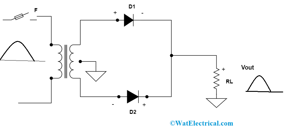
An ac source voltage is applied to the transformer coils. The input voltage makes the primary ends of a transformer to become positive and negative consecutively. With the passage of positive ac signal, the diode D1 will be positive, the ground point is ‘0’, and P2 is negative. During this instance, D1 is forward biased and D2 is in other conditions (reverse biased). As per the concept of the P-N junction diode, at the time of the positive cycle, D1 will conduct and D2 will not. So, current flows are in the direction of P1-D1-C-A-B-GND. Finally, the output is calculated across RLOAD.

full-wave rectifier-for-positive-half-cycle
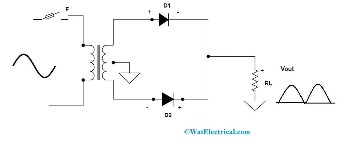
Whereas with the passage of negative ac signal, the diode D2 will be positive, the ground is zero reference point, and P1 is negative. During this instance, D2 is forward biased on and D1 is reverse biased. As per the concept of the P-N junction diode, at the time of the positive cycle, D2 will conduct and D1 will not. So, current flows are in the direction of P2-D2-C-A-B-GND. Finally, the output is calculated across RLOAD.

full-wave rectifier for negative half cycle
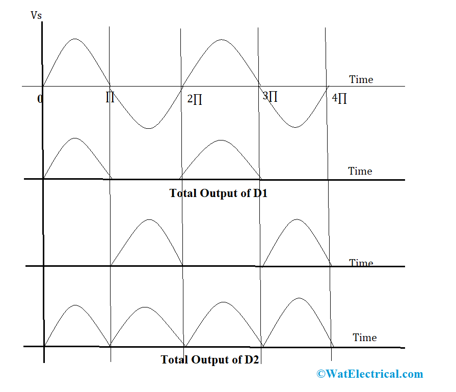
When the current flow across +ve and -ve cycles are compared, RLOAD receives the same output. So, it is concluded that the frequency of rectified output voltage is double the applied frequency. So, the result is rectified, has a dc component signal and many ac components of small amplitudes. With the resultant output, peak current, DC output voltage, RMS value of current, rectification efficiency, ripple factor, and regulation values can be known.
The output waveforms of full-wave center-tapped rectifier are as below:

output-waveforms
Full Wave Centre Tapped Transformer Working
A Centre Tapped transformer operates in general to that of a normal transformer. The variation lies behind that secondary winding is separated into two sections, where two separate voltages can be developed all across the two-line edges. When there is an additional connection of wire exactly at the center of the transformer’s secondary winding, it is termed as a center-tapped transformer.
Connecting an extra wire to the center point of the transformer forms the neutral point for winding. Because this is called a center-tapped transformer and so two voltages are produced where these two have a similar magnitude and opposite polarities. Here, one portion of the voltage will flow from line 1 to neutral and the other from neutral to the second line. When the connection of load is between two lines, then the resultant voltage is the sum of two.
Full Wave Centre Tapped Rectifier-Equations
There are various equations to be represented for center-tapped rectifier where the below-stated equations are the characteristics of this rectifier and those are:
Ripple Factor
It is the characteristic used to know the number of ripples those are in the resultant DC wave and it is denoted as
Kf = sqrt [(Vrms/VDC)2 -1]
On solving this Kf = 0.48
Rectifier Efficiency
It defines the ability of the rectifier that how effectively AC current is transformed into DC current. A maximum value implies as good rectifier and it is expressed as
ŋ = output PDC/input PAC
For a full-wave rectifier, the efficiency will be nearly 81%.
Form Factor
It is defined as the proportion of IRMS to IDC. It is denoted as
F.F = IRMS/IDC
For a full-wave rectifier, the value is 1:11
Peak Inverse Voltage
It is defined as the voltage of the diode when operated in reverse bias condition. For a center-tapped rectifier
PIV across D2 and D1 are = 2Vm
Advantages/Disadvantages
The full-wave center-tapped rectifier advantages/disadvantages are stated as follows:
The advantages are
- Compared to a half-wave rectifier, a full-wave rectifier has more efficiency. It means the transmission of AC to DC is done more effectively.
- In a full-wave center-tapped rectifier, both the positive and negative cycles are utilized. Thus, there will be no signal wastage.
- It has fewer ripples
The disadvantages are
- As because of center tapping, the circuit is costly and also uses more space.
Full Wave Centre Tapped Rectifier Applications
The applications are
- These rectifiers are employed in AC to DC transmissions
- As because of enhanced efficiency, these are implemented in power supply units
- In the context of functioning on the equipment such as LED’s or it might be motors where these kinds of rectifiers are employed.
Know more about Silicon Controlled Rectifiers MCQs.
FAQs
1). What is the simplest type of rectifier?
An electronic tool that is used for AC to DC transmission is a rectifier and the simplest kind of rectifier is a half-wave rectifier.
2). What is the difference between the rectifier and the converter?
Both the circuits are used for transmission of current from one form to another. A rectifier is used for AC to DC conversion and convertor for DC – AC conversion.
3). Which rectifier requires four diodes?
A bridge full-wave rectifier makes use of four diodes.
4). Which transformer is used in a full-wave rectifier?
For a full-wave rectifier, a center-tapped transformer will be utilized.
5). How does a full-wave rectifier differ from a center-tapped rectifier?
The operation of these two rectifiers seems to be almost similar whereas the variation lies in using the number of diodes. So, this is the complete and detailed analysis of how a center-tapped full-wave rectifier operates. So the other question which arises in this concept is how a center-tapped full-wave rectifier is formed using two half-wave rectifiers?