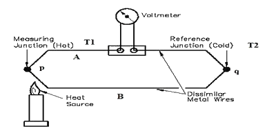
To know about what is a thermocouple we have to know of its definition. Thermocouple can be defined as a device comprising of at least 2 joined metals which forms 2 junctions. One of the junction is connected to the body of the device whose temperature is required to be measured, while second is connected to an entity whose temperature is already known. The unknown temperature junction is known as the measuring or hot junction while the known temperature junction is known as reference or cold junction.
Therefore, thermocouple can be referred to as a device which has capacity to measure the temperature of an unknown entity with reference to the entity whose temperature is known. One of the key applications of thermocouple is to measure the voltage difference or EMF of a circuit.
Working Principle of Thermocouple
There are a total of 3 effects on which the principle of operation of thermocouple is based. All of three effects are Thomson, Peltier, and Seebeck which are explained below in detail.
- Thomson Effect: The Thomson effect is dealing with two metals or entities which are join together for making 2 specific junctions. There is an existence of potential within the circuit because of which the temperature gradient side by side whole length of the conductors.
- Peltier Effect: The Peltier effect is dealing with two metals or entities which are not alike and are joint together for formation of 2 junctions. An EMF is generated among the circuitry because of the temperature difference among the two junctions.
- Seebeck Effect: The seebeck effect is dealing with two metals or entities irrespective whether alike or dissimilar are joint together. An EMF is then generated among the formed junctions which will decides the difference in temperatures of the entities or metals.
Working of Thermocouple
The following are circuit diagrams of Thermocouples.

Thermocouple Circuit
Here is Thermocouple Principle in discussed in detail. The Construction of Thermocouple is already shown in first figure which is comprising of two different metals named A and B joint together forming 2 specific junctions named p and q having temperatures T1 and T2. Both temperatures are maintained well. The formation of thermocouple is not possible without formation of junction and as depicted from figure, both junctions are being maintained at dissimilar temperatures, therefore forming Peltier effect and an EMF is generated through circuitry.
In case if the temperature of both of the junctions is same then there is an equal however opposite EMF generation on both sides of the junctions and the total current which is flowing across junctions is equal to Zero. However, if the junctions to be maintained at dissimilar temperatures, then an EMF sum will not be Zero and some current will be flowing across the junctions. It is to be remember that the total current flowing through circuit is totally dependent on the types of metals used for the circuit along with the junctions formed.
Devices for Measuring EMF of Thermocouple Circuit
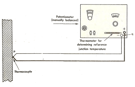
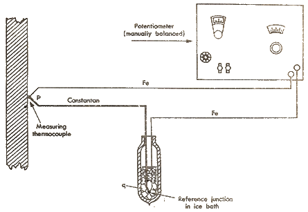
There can be many devices which may be used for the measurement of EMF of circuit of thermocouple. The extent to which EMF is developed in the circuitry of thermocouple is depending on the metals, however mostly the amount of EMF is very small, usually in millivolts. Therefore, the sensitivity of the device measuring EMF is very important. There are a total of 2 devices which are mostly used for the measurement of EMF known as Voltage balancing potentiometer and galvanometer.

Thermocouple Diagram
The thermocouple diagram below are showing devices for the measurement of EMF in the circuit of thermocouple. Here, the p junction is to be connected with the metal whose temperature is unknown while the q junction is to be connected to the metal whose temperature is known or the reference metal. In some cases the reference junction has to be connected to an ice bar to maintain its temperature as that of an ice as shown in figure below. The device for measuring EMF can be easily calibrated in reference to input temperature so that the device may get calibrated measurement instantly.

Equations of Thermocouple Circuit
As already explained in detail that a thermocouple is a device which is composed of two different metals or entities which are joined together for making a junction which is also known as measuring end. The metals are known as thermo-elements. These metals are also sometimes referred to as thermocouple’s legs. Both ends of the junctions are distinguished from each other through names of negative and positive ends. There are a total of two temperatures T1 and T2 which has been mentioned earlier. This can be shown in figure below for measurement of thermocouple output.

Thermocouple Output Measurement
As there is a difference of temperature among both tail and junctions of thermocouple, therefore difference of voltage has to be measured amid the 2 thermo-elements of thermocouple at the end of tail. This makes thermocouple as a transducer of temperature voltage. The relationship of voltage difference among the tail and junction of thermocouple is given through following equation.

Thermocouple Equation
Here, EMF is known as the electro motive force or also known as voltage that is produced through thermocouple at tail while T1 and T2 are the temperatures which are taken from the measuring end and reference end while S12 is known as the coefficient of seebeck of both metals of thermocouple. The coefficient of seebeck is highly depending on the material which is used for the composition of metals of thermocouples. From the equation mentioned above it can be deduced that:
- There is a null voltage which is being measured in case if both thermo-elements are composed of the same kind of material. Therefore, there is a need to make the thermo-elements composed of dissimilar materials in order to measure some temperature through sensing device.
- There is a measurement of null voltage again in case if there is no difference of temperature existence among junction end and tail end. Therefore, there must be some difference of temperature for the operation of thermocouple.
- The coefficient of seeback is highly dependent on temperature.