Either it is household or business necessity, we require sometimes to know the regulation and measurement of some physical conditions. For instance, in a diary organization, we require to calculate the humidity and temperature levels to maintain good product quality and accurate temperature levels for the product. So, these changes have to be transformed into electrical quantities, and then those need to be amplified. So, the amplifiers that are employed for this purpose are termed as “Instrumentation Amplifiers”. This article clearly explains to you the concept of instrumentation amplifier derivation, definition, it’s working, and others.
What is the Instrumentation Amplifier?
Instrumentation Amplifier which is abbreviated as In-Amp comes under the classification of differential amplifier that is constructed of input buffered amplifiers. These buffer amplifiers reduce the factor of impedance matching and making the amplifiers especially appropriate for measuring purposes. The signals those have similar potential values on both sides of the input will be canceled and the signal those have potential variation will be amplified.
This amplifier is mainly used within the frequency range of 1MHz thus delivering high gain at the output. Removing the CMMR value in the input signal, it amplifies signals. In-Amp also has multiple features such as minimal DC offset values, high level of input impedance, CMMR, open-loop gain, and minimal noise.
Working of Instrumentation Amplifier
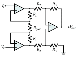
The below circuit of In-Amp describes the working principle of the amplifier. Here, the amplifier is constructed using two operational amplifiers having V1, V2 as input voltages, and O1 and O2 as outputs of op-amp 1 and op-amp 2. Three resistors R1, R2, and R3 are used and at the output is delivered through the difference amplifier and Vout is considered as the amplification output of the input signals.
As the two operational amplifiers placed at the input stage draws no amount of current, the voltage drop is in linear proportion to the voltage variation between input voltages. This develops current which flows through the resistors and the developed voltage is supplied as input to the differential amplifier.
Schematic Diagram Of Instrumentation Amplifier
Here, Rg is the external resistor that is placed in between the IC pins. When the pins are not connected, then amplifier gain will be one, but with different resistors, various values of gains can be obtained. The current flowing through Rg and R1 will be preferably similar because the current at the input stage of the operational amplifier is null.
This is a brief about In-Amp working. From the circuit, an instrumentation amplifier using op-amp derivation can also be done and it is as below:
The output is given by
VO = (R3/R2)/(O1-O2)
By considering only the input side of the instrumentation amplifier, the derivations for O1 and O2 can be also known and the input stage is as follows:
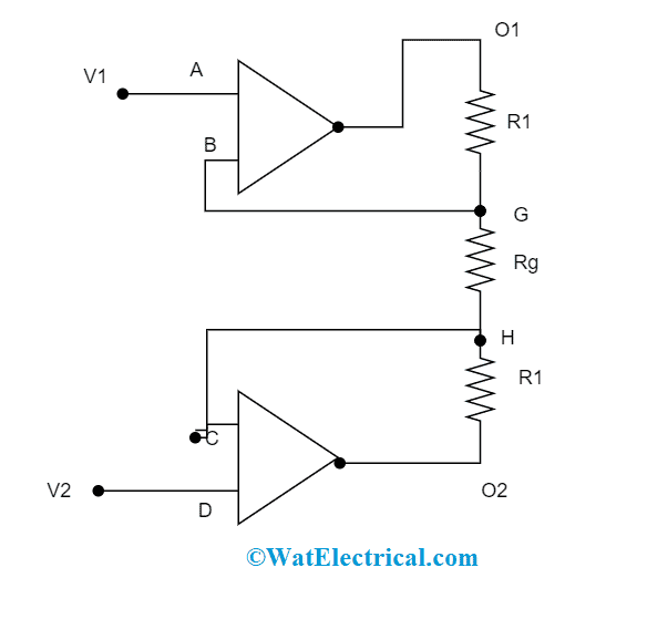
Input Stage Of Instrumentation Amplifier
As per the theory of virtual short, the potential voltages at the nodes A and B is V1. So, the output delivered at node G is also V1. In the same way, as per the theory of virtual short, the potential voltages at nodes C and D are V2. So, the output delivered at node H is also V2. As because current at the input stage of the operational amplifier is null, the current flow through the resistor Rg and R1 are the same. When the principle of Ohm’s law is applied between E and F nodes, then the current flow is given by
I = (O1 – O2)/(R1+Rg+R1) = (O1 – O2)/(2R1+Rg)
As there is no current flow through the two input operational amplifiers, the current flow between G and H is
I = (VG – VH)/Rg ~ (V1 – V2)/Rg
From the above two equations,
(O1 – O2) = [(2R1+Rg) (V1 – V2)]/Rg
When the output at differential amplifier is considered then
Vout = (R3/R2)*(O1 – O2)
So, (O1 – O2) = (R2/R3)Vout
Finally, (R2/R3)Vout = [(2R1+Rg) (V1 – V2)]/Rg
= Vout = (R3/R2) [(2R1+Rg)/Rg](V1-V2)
This is the derivation and the output of the instrumentation amplifier
The two conditions that have to be considered here are the gain of the In-Amp can be regulated by varying the value of Rg. And differential amplifier provides signal attenuation for the In-Amp.
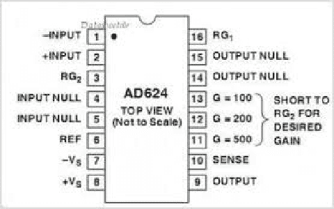
In-Amp IC
AD624 is the one In-Amp IC having the characteristics of minimal noise, increased precision rate, and principally constructed to implement in pressure transducers, load cells, gauges, and many others. The other features such as minimal gain of temperature coefficient, increased linearity allow this IC even to implement in the data acquisition networks. This IC functions at an input and output voltage drift values of <0.25 µV/°C and 10 µV/°C correspondingly. The CMMR value of AD624 is 130dB when the gain is 500 and the maximum non-linearity obtained at unity gain is 0.0001%. Furthermore, the instrumentation amplifier IC has extensive AC performance.
In-Amp IC
The maximum rating values for this In-Amp are as follows:
- The supply voltage is of ±18 V
- Input voltage is of Vs
- Functional temperature range is in between -250C to +850 This is the range of AD624A/B/C whereas for AD624S, the range is in between -550C to +1250C
- The range of storage temperature is -650C to +1500C
- The IC has internal power dissipation range of 420mW
- The time taken for output short circuit is of indefinite
Few of the input consideration those has to be considered are:
- When there is the condition is input overload the, the gain will be Rg = 100Ω and the two diodes have a voltage drop of ±2V in any of the directions
- Under the scenario of safe overload, the maximum overload voltage lies in the range of ±5V
- The input voltage level should not be ahead of the supply voltage level
- For this AD624, it can manage up to ±10V of overloads and it shows no complication for the device.
This is a brief explanation of the instrumentation amplifier IC.
Advantages of In-Amp
A few of the advantages of the instrumentation amplifier are
- As the In-amp have increased CMMR value, it holds the ability to remove all the common-mode signals
- It has minimal output impedance for the differential amplifier
- It has increased output impedance for the non-inverting amplifier
- The amplifier gain can be simply modified by adjusting the resistor values
- To modify the circuit gain, just a resistor change is enough and no need to modify the whole circuit
Applications of Instrumentation Amplifier
When an In-amp is embedded with a transducer bridge, it can be employed in multiple applications and those applications are termed as data acquisition systems.
- Used in temperature controllers
- Temperature Indicators
- Employed in light intensity meters
- Used in the gaming industries
- They have extensive usage in EEG and ECG instruments
- Used in hand-held batteries
Difference between Operational Amplifier and Instrumentation Amplifier
Below are the foremost differences between op-amp and In-Amp
| Operational Amplifier | Instrumentation Amplifier |
| It comes under the classification of integrated circuit | It comes under the classification of a differential amplifier |
| It needs just a single op-amp for the construction | It needs 3 op-amp’s for the construction |
| It has a gain of (V1-V2)*some pre-determined gain | An input voltage of 1 volt delivers a gain of 50 |
Know more about Active Low Pass Filter.
Know more about Operational Amplifier MCQs.
On the whole, this is the detailed explanation of instrumentation amplifiers. Here, we got clear information on In-Amp working, definition, derivation, In-amp using the operational amplifier, its applications, advantages, and In-amp integrated circuit. Also, know about what the practical applications are of the instrumentation amplifier?