Initially, ohmmeters were evolved based on the design construction of a meter known as “Ratiometer”. Ohmmeters under this classification only calculate the value of resistance because they are not simply integrated into the multimeter construction. Insulation testers which depended on a hand moved generator also works on a similar operation. This makes sure that indication was completely autonomous of the developed voltage. Following this, various designs of the ohmmeter supplied a tiny battery to provide a voltage to the resistance through the galvanometer in order to calculate the current values using resistance. Let’s have a clear thought on what an ohmmeter is, its operating principle, types, and benefits?
What is an Ohmmeter?
The ohmmeter is used to measure the quantity of electrical resistance between two points and this value is expressed in terms of ohms. The resistance which has to be known can be either in series or parallel connection with that of the device. In the parallel connection, the device draws high current because resistance is increased. Whereas, in series connection, the device draws less current because resistance is increased. Micro Ohmmeters are used for knowing the mess resistance values and the mega ohmmeters are used to know high resistance values. This device provides enhanced convenience to measure the values, but the results are not so accurate.
Ohmmeter Working Principle
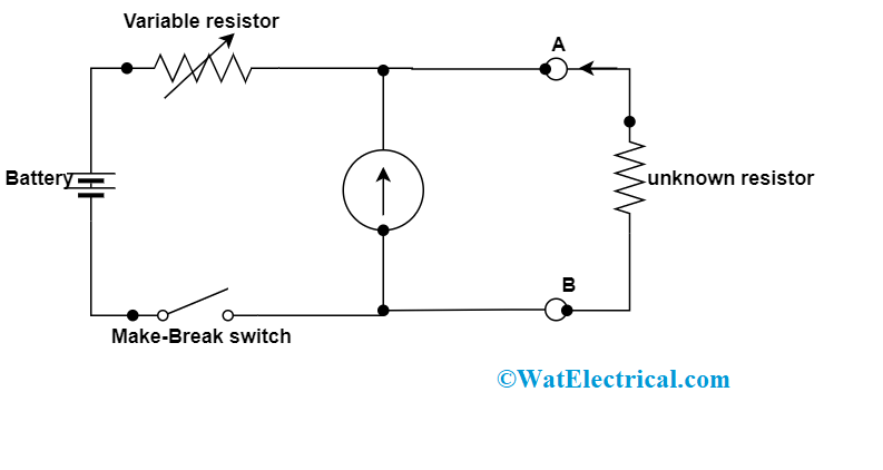
Using a battery and a series variable resistor, readings are known through this device. At the terminal end, the resistance that has to be calculated is connected. With the connection of output resistance, current flows in the device and the deflection can be measured.
When high resistance values are to be calculated, then the current flow will be less and the output will be maximum resistance. In the same way, when fewer resistance values are to be calculated such as zero the device reading is positioned to zero value and this gives less resistance.
Types
With this device, one can know the approximate values of the resistance. Depending upon the application, the ohmmeters are mainly categorized as three types and they are as follows:
- Series ohmmeter
- Shunt ohmmeter
- Multi-range Ohmmeter
Let us have a clear discussion of these types of ohmmeters.
Series Ohmmeter
In this type, the resistance value of the circuit that has to be known should be in series connection with the meter. Through the d’Arsonval movement that is in parallel connection to the shunt resistor, the resistance value can be known. And the resistance value for the device that has to be known should be in series connection in between A and B ends. For the series connection, the circuit diagram can be shown as follows:

Shunt Type Ohmmeter
When the unknown resistance value is ‘0’, then there will be the maximum current flow across the meter. In this case,
- When the value of unknown resistance is zero the large current flow through the meter and A and B endpoints will be short-circuited. Then the current that flows through the meter will be classified between R1 and R2 resistor. And now, when the R2 value is changed in the way that the whole current stream across R1, then the meter reading is termed as full-scale deflection. So, the meter’s deflection is shown as 0Ω.
- When the value of unknown resistance is infinite, no current flows across the meter and A and B endpoints will be open-circuited. Then the current that flows through the resistor R1 is zero. And now, the meter reading is termed as null deflection. So, the meter’s deflection is shown as ∞Ω.

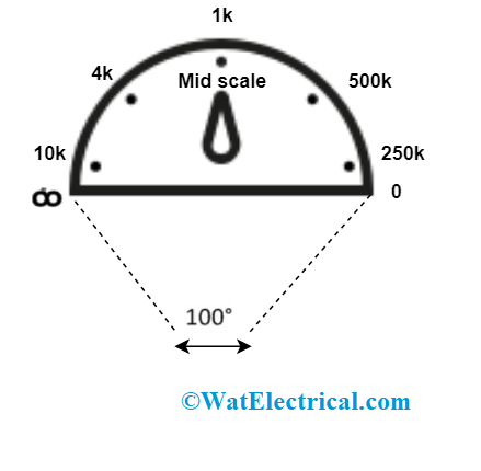
Calibration Scale Series
Like this, by modifying the values of unknown resistance, the meter reading will show multiple deflections. Thus correspondingly, we can signify these deflection values as per the resistance values. The calibration scale of the series ohmmeter has indications ranging from 0Ω to ∞Ω at both the ends of the scale. Mostly, this device is utilized to calculate maximum resistance values.
Shunt Ohmmeter
In this type, the resistance value of the circuit that has to be known should be in parallel connection with the meter. Here, the basic measuring meter, the battery, and the variable resistor are the essential components of shunt ohmmeter. The value of the resistance that has to be known is positioned between A and B ends. For the shunt connection, the ohmmeter circuit diagram can be shown as follows:

Shunt Type Ohmmeter
- When the value of unknown resistance is zero then the A and B endpoints will be short-circuited. As because of this, I1 current stream across the endpoints A and B. In this situation, PMMC galvanometer reading will be zero current. So, the null deflection in the galvanometer is signified as 0Ω.
- When the value of unknown resistance is infinite then the A and B endpoints will be open-circuited. As because of this, no current stream across the endpoints A and B. In this situation, PMMC galvanometer reading will be I1 current. When the variable resistor value is modified until it reads full-scale deflection. Then, the full deflection in the galvanometer is signified as ∞Ω.

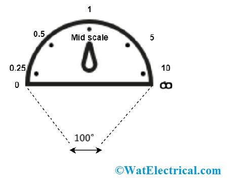
Calibration Scale Shunt
Like this, by modifying the values of unknown resistance, the meter reading will show multiple deflections. Thus correspondingly, we can signify these deflection values as per the resistance values. The calibration scale of the shunt ohmmeter has indications ranging from 0Ω to ∞Ω at both the ends of the scale. Mostly, this device is utilized to calculate minimal resistance values.
Multi-Range Ohmmeter
In this kind of ohmmeter, the range is maximum. Through the help of a variable, the range can be selected as per our requirement.
For instance, when we would like to calculate the value of resistance below 10Ω. Then the resistance whose value to be known should be in parallel connection to the meter. The magnitude value of the resistance is known using the deflection in the pointer.
So, these are the types of ohmmeter. Upon the requirement to calculate either high or low values resistance, the corresponding type is used.
Applications
As this basic instrument to be required in almost all the applications there are extensive uses of the ohmmeter. Few of those to be described below:
- This meter is implemented to make sure the regular flow of the circuit where this corresponds that in the conditions of extremely high or low current flow across the circuit, then it will get disconnected.
- Mostly, this device is utilized in the electrical laboratories either for the purpose of testing electric tools or for other purposes.
- Also, used in tiny integrated circuits for the purpose of fixing issues in printed circuit boards or in other sensitive instruments.
FAQs
1). What is the ohmmeter scale?
It is the calibration scale that represents resistance values from zero to infinite and this is deflected depending on current values.
2). Is ohmmeter the same as multimeter?
An ohmmeter is a device that particularly measures resistance values, whereas multimeter is the integration of both voltmeter and ohmmeter and both volt and resistance values are calculated.
3). What is a low resistance ohmmeter?
This is the micrometer which is used to measure micro values of resistance.
4). What are the different parts of the ohmmeter?
The parts are variable resistor, an unknown resistor, a battery, a switch, and the basic meter.
5). How much voltage does an ohmmeter use?
This device generally calculates the flow of current and mostly 1.5V is used by the battery to operate.
Please refer to this link for Ohmmeter MCQs.
This is all about an overview of an ohmmeter, its operating principle, types of the device, how they are connected, and various applications. From a small range of devices to huge devices, these are mostly implemented in various industries and domains. The further question that arises here is what are the practical applications of an ohmmeter?