One of the most crucial devices in the history of the electronics domain is Amplifier. It is the device that acts in response to a minimal amount of current, voltage, or power and generated a larger output signal. This scenario is called amplification and it can be delivered by various devices such as generators, vacuum tubes, transformers. But these, people also utilize solid-state microcircuits in the place of amplifiers. In most situations, the output delivered by a single amplifier is not adequate and in these scenarios, the cascade amplifier is used. So, this article clearly explains the concept of Cascade Amplifier, its theory, the detailed analysis behind the device and its applications.
What is Cascade Amplifier?
Cascade amplifier is also termed as a multistage amplifier. It is the two-port network that is designed through a chain of amplifiers. Here, the output of one stage is fed as input to the next stage in a chain format. Because of the purpose of loading in between two stages, it is somewhat intricate to calculate the gain and it has imperfect coupling.
Cascade Amplifier Theory
Cascading amplification is mostly preferred in the situations of long-distance, electronic controlling, radar, television, and in many calculating instruments. To cascade amplifiers, there exist multiple types of schemes and it is based on the signal behavior in the amplification procedure. When compared with vacuum tubes amplification, solid-state of microelectronics holds more benefits for directly coupling multiple amplifiers. Even transformers are also implemented for cascade amplification, but they have heavy constructional design and expensive too.
In correspondence to the input signal, an electronic amplifier delivers an amplified output signal and this is termed to be linear kind of amplification. When there happens any modification in the shape of the signal, in the process of amplification, then amplitude distortion takes place. Or else when all the frequency ranges are not equally amplified by the amplifier, it is termed as frequency distortion.
Based on the type of connection of amplifier phases, there are various kinds of cascading amplifiers and those are as below:
- RC cascaded amplifier (Resistor – Capacitor)
- LC cascaded amplifier (Inductor – Capacitance)
- RL cascaded amplifier (Resistor – Inductor)
- Transformer cascaded
- Direct cascaded
- Optical cascaded
Transformer cascaded amplifiers are probably termed as tuned amplifiers. Staggered tuning is the one cascaded amplifier where every individual phase frequency is tuned to a certain range so as to enhance the gain and bandwidth of the amplifier.
Gain
As there are multiple stages in a cascade amplifier, the gain of the whole amplifier is known by multiplying the gain of each individual stage.
Gain = G1 * G2 * G3*……..*Gn
Where G1, G2, G3, and Gn are the gains of individual amplifiers. When the gain of the cascaded amplifier is calculated in decibels, then the overall amplifier gain is given by
Gain (dB) = G1 + G2 + G3+ ……+Gn
Cascade Amplifier Analysis
To design complicated systems, there are mainly three fundamental configurations in the cascade design. Through the cascading of amplifiers, the circuits deliver enhanced performance and greater efficiency. The basic analysis of the cascade amplifier can be known through the below.
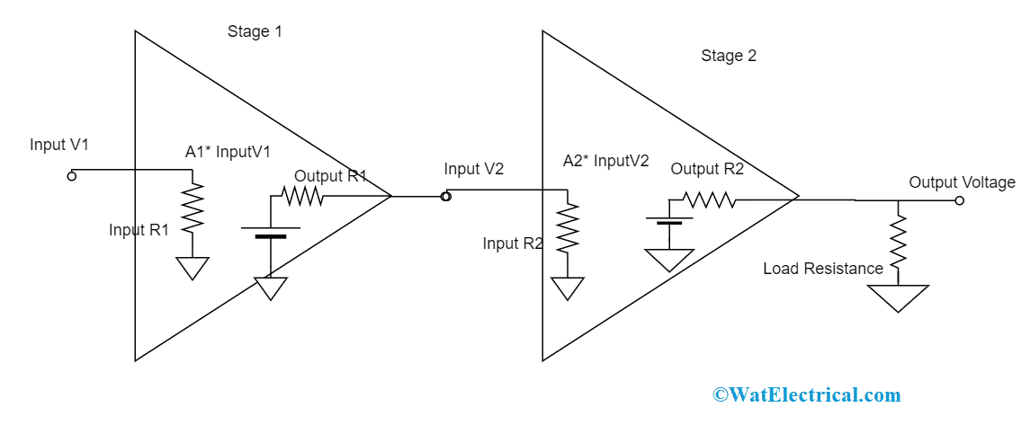
In the two-phase cascading amplifier, the required consideration is what is the condition when the non-ideal amplifiers are placed in a series position. From the below figure it is known that both the input and output resistances comes into operation by minimizing the circuit gain. When the input and output resistance values are 0 and infinity and the amplifiers have A1 and A2 gains, then the entire gain of the circuit is A1*A2. Let us now analyze that the gain thinking nothing regarding the input and output resistances of each individual phase, considering those as voltage dividers in between the two phases and in between the last stage and the load at the output.

Basic Two Stage Cascade Amplifier
The voltage between the two stages is
Input V1 = A1 * Input V1 (Input R2/(input R2 + output R1))
While the Vout in between output R and load resistance is
Output V = A2 * Input V2 (RL/( RL + output R2))
So, the entire gain of the circuit is given by
Vout/Vin = A1 * A2 [(Input R2/(input R2 + output R1))] * [(RL/( RL + output R2))]
With the above overall gain equation, it minimizes to Av = A1* A2 when we consider the input and output resistance values as zero and infinity. In most of the cascaded amplifier stages, when the input resistance is either in Mega or Giga Ohms and output resistance is in the range of 10 -100Ω, then the circuit gain is the product of A1 and A2.
For instance: when input resistance = 1MΩ and output resistance = 100Ω and load resistance is 1MΩ, then the gain is
Vout/Vin = A1 * A2 [(1M Ω /(1M Ω + 100 Ω)] * [(1M Ω /(1M Ω + 100 Ω)]
= 0.9998A1*A2 ~ A1*A2
CE/CC Cascading Method
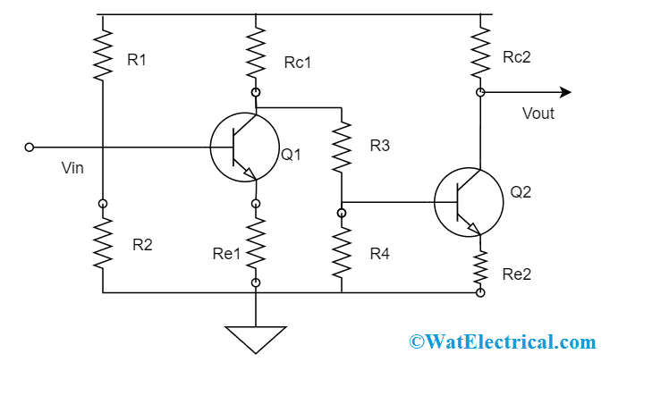
With the cascading method of common emitter which is followed up with a common collector, the stage delivers a better voltage amplifier. The CE resistance is correspondingly high whereas the CC (output resistance) is correspondingly low. The transistor Q2 stage provides no increase in the gain of the voltage but offers a close minimal resistance output so the gain is almost not dependent on load resistance values. While the maximized resistance at the Q1 stage shows that the CE voltage is not dependent on input source resistance values. Many CE stages might be cascaded with that of emitter follower phases so that this cascading procedure lessens attenuation that happens because of interphase loading.

CE Cascade Amplifier Circuit
Advantages
The cascade amplifier advantages are:
- Enhanced performance and efficiency
- Maximum flatness levels
- Minimal noise figure in the range of 1-10GHz
- Increased gain
- Increased bandwidth allows the devices to be widely employed for high-voltage amplifier purposes
- Hight input and output impedances
- Used for the better amplification of signals
Know more about Stagger Tuned Amplifier.
So, this is all about the concept of the cascade amplifier. Used in applications such as television systems, wideband amplifiers, and in good isolation purposes, these amplifiers hold more prominence in the electronics industry. But the only disadvantage is that when numerous stages are cascaded, the bandwidth will get reduced. The question that arises here is to know what are the other configurations in the cascade amplifier and how they are functioned?