A DC motor along with servomechanism (closed-loop control system) acts as a servo motor which is basically used as a mechanical transducer in the automation industry. Based on its accurate closed-loop control, it has versatile applications used in many industries. The DC servo motor definition is, a motor that is used in servo systems is known as a servo motor. A servo system is a closed-loop system where the feedback signal (position, velocity, acceleration, etc.) drives the motor. This signal acts as an error and based on controller, accurate position or velocity is achieved. The motors are coupled to an output shaft (load) through a gear train for power matching. Servo motor acts as a mechanical transducer as they convert an electrical signal to an angular velocity or position.
DC Servo Motor Working Principle
Consider the following block diagram which consists of the different blocks where the function of each block is explained in brief.
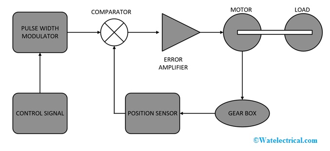
block-diagram-of-servo-motor
Motor
It is a normal DC motor with its field winding separately excited. Based on the nature of excitation, it can be further classified as field controlled and armature controlled servo motors
Load
It is connected to a mechanical shaft of the motor. It could be any industrial load or a simple fan load.
Gear Box
It acts as a mechanical transducer to convert the output of the motor in the form of position, acceleration or velocity based on application.
Position Sensor
It senses the position of the rotor and feeds it to the comparator. Commonly used sensors are hall effect sensors.
Comparator
It compares the output of a position sensor and a reference point to generate the error signal and feeds to the amplifier. If the motor runs with exact control, then no error is zero. The gearbox, position sensor, and comparator make the system closed loop.
Amplifier
It amplifies the error from the comparator, for feeding into the motor. It acts like a proportional controller where the gain is amplified for zero steady-state error.
Control Signal and Pulse Width Modulator
Based on the feedback signal, controlled gives the input to pulse width modulator which modulates the input of motor (voltage or field excitation) for exact control or zero steady-state error. The pulse width modulator further uses a reference waveform and comparator to generate pulses.
By making the system closed-loop exact position, acceleration or velocity is obtained. The name servo motor implies a controlled motor that gives the desired output because of the effect of feedback and controller. The error signal is amplified and used to drive the servo motor. Based on the nature of producing control signal and pulse width modulator, servo motors can have advanced controlled techniques using digital signal processors or FPGA chips.
Characteristics of DC Servo Motor
The characteristic or in other words the requirements of a servo motor are:
- The inertia of the servo motor should be less for precision and accuracy
- It should have a fast response which can be obtained by keeping high torque to weight ratio.
- The torque-speed characteristics should be linear
- Four quadrant operation is desirable by using further converters.
- Stable operation
- Robust nature.
Types of DC Servo Motor
Based on the nature of electric supply servo motors can be classified as AC and DC servomotors. Again based on speed control, the DC servomotors can be classified as Armature controlled and field controlled servomotors. The circuit diagram, block diagram and transfer function of these are given below:
Armature Controlled DC Servomotor Circuit Diagram
In this motor, the field current is held constant and armature current is varied to control the torque.
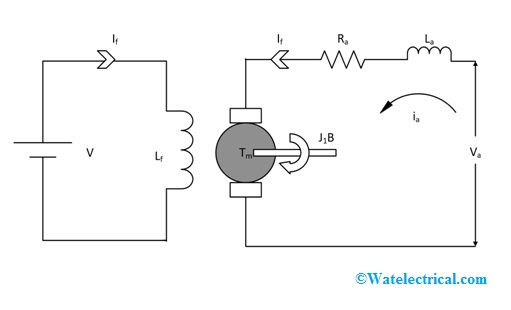
circuit-diagram-of-armature-controlled-dc-servo-motor
Let
Ra= Armature Resistance
La = Armature Inductance
Ia = Armature Current
Va = Armature Voltage
Wm = Angular Velocity
Eb = Back EMF
J = Moment of Inertia
If = Field Current
Lf = Field Inductance
Tm = Torque Produced
Eb = Back EMF produced by the motor
Applying KCL in the armature we get
Va = ia Ra + La *(dia/dt) + eb
The load torque equation is given by
J * (d2 θ/dt2) + B * (dθ/dt) = Tm = K1 ia
Substituting i_a in the second equation and converting into the Laplace domain, the transfer function of the DC servomotor can be obtained as below:
Transfer Function and Block Diagram
The block diagram of the armature controlled DC servo motor is shown below.
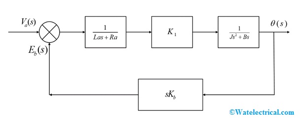
block-diagram-of-armature-controlled-dc-servomotor
The transfer function of armature controlled DC servo motor is shown below.
θ(s)/Va(s) = (K1/(Js2 + Bs)*(Las + Ra)) /1 + (K1KbKs)/(Js2 + Bs)*(Las+Ra)
Field Controlled DC Servo Motor Circuit Diagram
In this method of speed control, a variable input voltage is applied to the field winding of DC motor, while keeping the armature current constant.
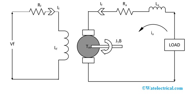
circuit-diagram-of-field-controlled-dc-servo-motor
Let
Rf = Field Resistance
Lf = Field Inductance
If = Field Current
Vf = Variable field voltage
θ = Angular displacement of the motor shaft
Tm = Torque developed by the motor
B = Coefficient of viscous friction
J = Moment of inertia
The field equation is given by:
Vf = if Rf + Lf * di/dt
Torque equation is given by
J * d2θ/dt2 + B * dθ/dt =Tm
Converting into Laplace domain, and substituting for field current we get the transfer function as:
Transfer Function and Block Diagram
The block diagram of field controlled dc servomotor is shown below.
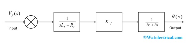
block-diagram-of-field-controlled-dc-servo-motor
The transfer function of field controlled dc servomotor is shown below.
θ(s)/Vf (s) = Kf / (sLf + Rf) * (s2J + Bs)
Due to the closed-loop system, armature controlled gives better performance as compared to field controlled which is the open-loop system. Also, the speed of response is slow in the field control system. In the case of armature controlled, the inductance of the armature is negligible, which is not the case for field control. Infield control, improved damping is not possible, which can be achieved in armature control.
Difference between Servo Motor and DC Motor
The following points may be regarded as the difference between the servo motor and DC motor
Servo motor | DC Motor |
| Servo motor works on the principle of the closed-loop control system, in which DC motor is also one of the components | A DC motor works on the principle of Lorentz’s Force Law, i.e. when a current-carrying conductor is placed in a magnetic field, it experiences a force. |
| Due to a closed-loop control system, servo motor would have higher precision and accuracy | This is not the case with the DC motor.
|
| The inertia of servo motor is less | The inertia of dc motor is less |
| A servomotor is more suited for automation and robotics industry | The DC motors have versatile applications |
| Servomotor need maintenance | A DC motor is rugged in nature |
| Servo motors are more costly compared to DC motors | DC motors are not expensive compared to servo motors |
DC Servomotor Applications
Because of its precise control and accuracy, servo motor has numerous applications, a few of them have been enlisted below:
- Automation Industry
- Robotic Industry
- Aviation
- Manufacturing Industry
- Pharmacy
- Food Services
- Toys and radio-controlled cars
DC Servo Motor Advantages and Disadvantages
The advantages of DC Servo Motor are
- Precise Control and Accuracy
- Stable Operation
- Fast Response
- Lightweight and portable
- Four Quadrant operation possible
The disadvantages of DC Servo Motor are
- Due to the complex circuit, reliability is less
- Due to closed-loop components i.e. amplifier, gearbox, etc. it is costly
FAQs
1). What is the transfer function of a Servo motor?
For armature voltage control
θ(s)/Va(s) = (K1/(Js2 + Bs)*(Las + Ra)) /1 + (K1KbKs)/(Js2 + Bs)*(Las+Ra)
For field control
θ(s)/Vf (s) = Kf / (sLf + Rf) * (s2J+ Bs)
2). What is the principle of the Servo motor?
The principle of DC motor is Lorentz Force law, according to which whenever a current-carrying conductor is placed in the magnetic field, it experiences a force. When a DC motor is placed in closed-loop with feedback, it forms a servo motor, which converts electrical signals to mechanical i.e. acceleration, position, etc.
3). What is the difference between the DC motor and Servo motor?
DC motor is an open-loop system whereas servo motor is a closed-loop system.
4). What is the effect of feedback on DC Servo motor?
By including feedback, a servo motor can achieve precise position or velocity or acceleration with zero steady-state error.
5). What are the advantages and disadvantages of a Servo motor?
Advantage are precise speed control, position, and acceleration. Disadvantages are costly and require maintenance.
6). What are the applications of a servo motor?
Automation, Robotic, Manufacturing, etc.
7). What is the difference between armature controlled and field controlled servo motor?
In armature controlled, armature voltage is varied by keeping field current constant. But whereas in field controlled, the field current is varied by keeping armature current constant. Armature control is the closed loop, whereas field control is an open-loop system
8). Voltage Equations of servo motor?
For armature control
Va = iaRa + La * dia/dt +eb
For Field control
Vf = if Rf + Lf di/dt
9). Torque equations of servo motor?
For armature and field control:
J d2θ/dt2 + B dθ/dt = Tm
Thus, this is all about an overview of what is a DC servo motor, Its principle, characteristics, types of servomotor, the difference between the servo motor and DC motor, advantages, disadvantages, and Its applications.