The very initial investigations led to the design of the machine are done by Andrew Gordon a Scottish scientist and Benjamin Franklin in the initial 1740s. This discovery required the usage of current and voltage for its development. Later, the contraption of battery by volta in 1799 made possible the design. This also required the cooperation of forces to produce a rotating captivating field. The cooperation of two forces is made possible to create a captivating field that can able to twist the rotor inside the captivating field. Thus, by the initiation of faraday’s rules of magnetic induction, a motor is found finally. Let us address DC shunt motor, working principle, operational features, speed control, characteristics, load test, and applications of DC shunt motor respectively.
What is a Shunt Motor
Definition: It is a type of motor that is used for constant load applications. Its winding is basically arranged in parallel with the armature winding. The figure that depicts the shunt type of motor is shown below.
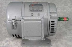
DC shunt machine
DC Shunt Motor Diagram
The circuit diagram that represents the shunt type motor is shown in the figure below.
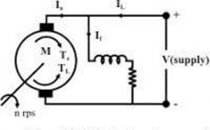
shunt motor
Working Principle
It works on the principle of Faraday’s law of electromagnetic induction. The field winding is connected in parallel to the armature winding. A DC supply is applied to the field winding across the armature. The armature conductors are placed under the influence of the magnetic field. This magnetic field is developed when the supply is given to the field winding. The armature conductors placed under the influence of magnetic field expertise the force. The current in the armature conductors on left portion experience inside current and the right portion experience outside current.
The force direction is found by Fleming’s Left-hand rule in the case of a motor. The current-carrying conductors experience force based on the corkscrew rule. According to this rule, the current inside the conductor experience a force in the clockwise direction and the direction of current outside the conductor experience a force in the anti-clockwise direction. The force from the magnets due to the current in the field winding will slightly deviate.
On the left portion of the armature conductor, the direction of the force on the conductor is clockwise that opposes the direction from the field and aid in the right potion. Similarly, the direction of current outside the conductor experience a force anti-clockwise opposes the field in the right portion and aid in the left portion. So, the resultant flux slightly deviates that enables the rotor to develop torque. This developed torque produces a twisting motion in the anti-clockwise direction.
Characteristics
The voltage equation corresponding to the DC shunt motor is given by
V = Eb + Ia Ra
Eb = V – Ia Ra
The relation between flux and the current through the shunt winding is given by
Φ α Ish
From the diagram, we can know that,
Ish = V/Rah
The relation for the speed of shunt type motor is given by
N α Eb
N α V – Ia Ra
The flux in a DC shunt motor is constant. Therefore, as Φ α Ish we can say that Ish is also constant.
The relation between the speed and the armature current derived from the above equations as
N α (V – Ia . Ra)
As the value of the armature current (Ia) increases the speed value decreases slightly. This can be observed in the characteristic curve drawn between the speed N and the armature current (Ia).
The characteristic relation between speed and armature current is shown in the figure below.
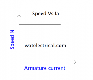
speed Vs Ia characteristics
The relation between the torque and the armature current is given as
T α φ Ia
As φ is constant in this type, T α Ia
The characteristic curve drawn between the torque and the armature current is shown in the figure below.
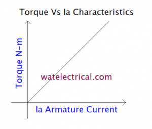
torque armature current characteristics
Speed Control
The speed control of this type of motor is achieved by varying either the armature current or armature resistance or by varying the terminal voltage applied.
The speed relation of Dc shunt type motor is given as
N α ( V – Ia . Ra )
When the armature current is increased the speed value can be decreased. Make sure that the armature resistance and terminal voltage should be maintained constant while varying the armature current. In the same way, while varying armature resistance the armature current should be kept constant including the terminal voltage. It can also be controlled by varying only the terminal voltage keeping the other variables constant.
Load Test
A direct test is applied for this type of motor and this test is also known as the Brake test. This test is used to determine the efficiency of the motor by which performance can be analyzed. Brake test is applied by putting some weight on the pulley of the motor. By applying load on to the motor the different values of the current and the voltage are recorded to find the efficiency. The efficiency of the motor is determined by using the formula Ƞm = (w (S1 – S2) 9.81) / VtIl * 100.
where w is the weight of the machine,
S1 and S2 denote the spring balance,
Vt is the terminal voltage,
Il is the line current.
The figure that depicts the load test on the motor is shown in the figure below.
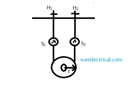
brake test
Applications
DC shunt motor is used in constant motor applications like the following
- lathe machines
- conveyor belts
- fans
- blowers
- weaving machines
- Centrifugal pumps,
- and spinning machines.
Thus, in this article, we had discussed what is a shunt motor. It is a type of motor whose winding is arranged in parallel with the armature winding and it is applicable for constant loads. Apart from this, we had also studied its working principle, circuit diagram, characteristics, speed control, load test, and applications. Here is a question for the readers, what are different types of the motor?
Leave a Reply