We know that the electric domain is huge, and it all turns around electrical circuits and networks. So, analyzing an electric circuit is sometimes simple and in some cases, it turns to be too complex because we need to find out unknown voltages and current values at every node in the circuit. In order to make the circuit analysis process easy, there were mainly two approaches which are mesh and nodal analysis. Both techniques make the process of analyzing a circuit simple thus reducing the time and complexity. And today, here we are going to discuss completely on nodal analysis procedure, its features, what are its properties, and nodal analysis examples.
What is Nodal Analysis?
Nodal analysis is also called Node-voltage analysis/Node analysis or branches current analysis. The definition of nodal analysis is said that it is a technique of knowing the difference in voltage between the nodes in an electric circuit using branch currents.
As a part of circuit analysis, the KCL principle is used when the nodal analysis is used whereas the KVL principle is utilized when mesh analysis is used. In nodal analysis, equations are written at every node making sure that branch currents at a specific node totaled to be ‘0’ and the branch currents are represented in the form of circuit node voltages. As a result, every branch corresponding relation should provide a current value in terms of voltage.
For instance, when Ibranch = Vbranch * G, here ‘G’ corresponds to the resistor’s admittance.
The features of nodal analysis are:
- Nodal analysis is a powerful mechanism, and it works depending on the similar concept of matrix analysis.
- This analysis is operated either in frequency or time domains but constrained for time-invariant systems.
- The circuit analysis can be done with ‘n-1’independent nodal equations when there ‘n’ nodes in the circuit.
- Nodal analysis is generally applicable for the networks that have multiple parallel circuits with a common ground terminal.
- Here, the total number of independent nodal pair equations required is one less than the total number of junctions present in the network.
- The non-reference nodes in the circuit have constant voltage values and the reference node stands as a reference for all the other remaining nodes in the circuit.
- At a particular node, the sum of currents entering into the node should be similar in value to the sum of currents leaving at that node.
- The total number of nodal equations and the total number of non-reference nodes in the circuit to be obtained are the same.
Step by Step Procedure of Nodal Analysis
Here is the step by step procedure of nodal analysis explaining analysis of a circuit.
- Find all the principal nodes present in the circuit and choose one as a reference node and this reference node acts as a ground terminal.
- Mark all the node voltages with regard to the ground terminal from all principal nodes other than the reference node.
- For all the principal nodes, write the nodal equations except for the reference node. The nodal equations are written using Kirchhoff’s current and Ohm’s law.
- Find the node voltages at each node and the node voltages can be obtained by solving the equations that are obtained in the above step.
- So, using node voltages the current and voltage values can be calculated for each element in the circuit.
Types of Nodes
To rewind, a nodal voltage is termed as variation in voltage between two nodes where a branch or component exists. Through nodal analysis, mathematical equations at each non-reference node can be known where the algebraic sum of currents at a node equals ‘0’.
And this section explains on types of nodes in nodal analysis which are mainly of two types.
Non-reference node
The node voltages are utilized in the analysis of the circuit.
Reference nodes and Types
Reference nodes are generally termed as ground terminal nodes, and these nodes stand as references for all other nodes in the circuit. It is also called a datum node.
Again, reference nodes are further classified as:
Earth ground node – In any electric circuit, if earth potential is considered as a reference node, then it is termed as an earth ground node.
Chassis ground node – This node acts as a shared node for more than one circuit.
Constructing a Matrix Equation
The below section explains constructing a matrix equation using nodal analysis.
To construct a matrix equation, it is required to use the KCL principle at every node in the circuit. Using Kirchhoff’s law, equations are written corresponding to voltage drop at multiple elements to the currents entering into the node. To write a matrix equation, follow the below steps.
- Draw a circuit diagram with the current values specified at every node
- Choose a reference node (which is generally ground terminal) and at every node write the variable for voltage corresponding to the reference node
- Use the KCL principle at each node and write equations w.r.t circuit impedance and voltages at adjacent nodes
- As per the obtained equations in the above step, rewrite those in matrix form and solve the matrix equation through the inverse matrix technique
To clearly understand the matrix equation procedure, let us consider an example of nodal analysis.
Circuit Diagram To Represent Matrix Equation Using Nodal Analysis
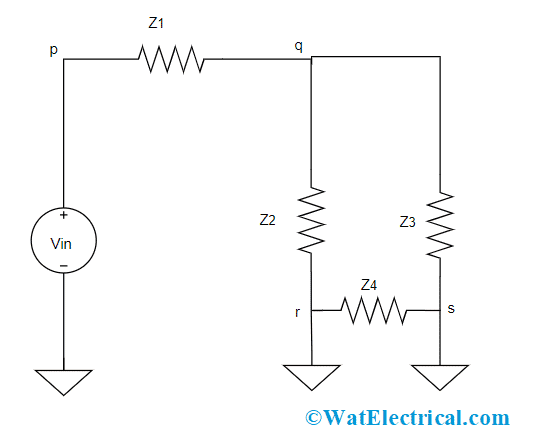
Consider the below circuit which consists of a voltage source, four individual nodes, and four impedance. Node ‘p’ is the input voltage that leaves the voltage at the other three nodes and those are to be known. Now, equations for voltages at every node has to be written and those are:
At node ‘q’
(Vp – Vq)/Z1 = (Vq – Vr)/Z2 + (Vp – Vs)/Z3
At node ‘r’
(Vq – Vr)/Z2 = (Vr – Vs)/Z4
At node ‘s’
(Vr – Vs)/Z4 + (Vq – Vs)/Z3 = 0
All the above three equations are re-arranged to get the matrix form
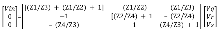
Matrix Equation
Vin = [(Z1/Z3) + (Z1/Z2) + 1] Vq – (Z1/Z2) Vr – (Z1/Z3) Vs
0 = -Vq + [(Z2/Z4) + 1] Vr – (Z2/Z4) Vs
0 = -Vr + [(Z4/Z3) + 1] Vs – (Z4/Z3) Vq
Arranging the above equations in matrix form gives
So, solving of matrix equation can be made easy by multiplying with the reverse of the coefficient matrix. As per the above circuit, there is a ground terminal that acts as a reference node where all the voltage variables are calculated corresponding to the reference node. The benefit behind this helps in closed circuit creation and sets the reference for the entire voltage variables present in the matrix.
Nodal Analysis with Current Sources
The nodal circuit analysis is so simple, and it can be clearly understood using below example:
Example: In the circuit, find the node voltages.
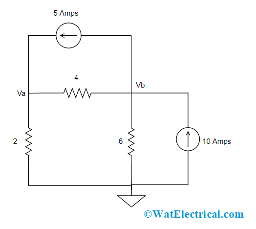
Nodal Analysis With Current Sources
Solution:
In the given circuit, we have two non-reference nodes (Node A and Node B)and one reference node (Node C).
First, apply KCL principle at Nodes A and B
At Node A
Ia = Ib + Ic
At Node 2
Ib + Id = Ia + Ie
Then apply Ohm’s law for the above two equations
Ia = Ib + Ic
- 5 = (Va – Vb)/4 + (Va – 0)/2
- 3Va – Vb = 20
Ib + Id = Ia + Ie
- (Va – Vb)/4 + 10 = 5 + (Vb – 0)/6
- -3Va + 5Vb = 60
Through elimination procedure, the above equations are solved to get values of Va and Vb
So, the node voltages are Vb = 20V and Va = 13.3V
Nodal Analysis with Voltage Sources
There are two scenarios in the voltage source condition:
Scenario 1: When a voltage source is used between non-reference and reference nodes, then the voltage at the non-reference node is set to be equal to the voltage of the source, and a similar analysis like current sources is followed
Scenario 2: When a voltage source is placed between two non-reference nodes, then a supernode is formed.
So, here comes the question of what is supernode?
A node is termed a supernode when a voltage source is placed between two non-reference nodes. It is considered as a voltage source.
The properties of supernode are:
- A supernode does not possess voltage by itself
- In solving the supernode, either KVL or KCL principle can be applied
- Any component can be in parallel connection with voltage source so that a supernode is formed
- The functionality of Kirchhoff’s current law for supernode is the same as a general node
Super Node Example
With the below example, the supernode analysis can be clearly understood.
Example: Find the node voltages in the below-given circuit
Super Node Example
Solution:
In the circuit, we have a supernode with two voltage sources, a resistor, and two nodes node A and node B. For the supernode, when KCL is applied, we have
2 = Ia + Ib + 7
Then apply, KVL principle for Ia and Ib using node voltage variable, then
2 = [(Va – 0)/2)] + [(Vb – 0)/4]+ 7
8 = 2Va + Vb + 28
Vb = -Va – 20
In order to know the relation between Va and Vb employ KVL, then
-Va – 2 + Vb = 0
Vb = va + 2
From the above equations, we have
Vb = va + 2 = -Va – 20
3Va = -22
Va = -7.3Volts
Then Vb = Va + 2
Vb = -5.3 Volts
Here, a resistor in the circuit will not impose any problem in analyzing the circuit because is connected only across supernode.
Nodal Analysis by Using Dependent Sources
A dependent source can either be a current or voltage source where the value of the source is based on the current or voltage values in the circuit. Dependent sources are mainly implemented in the analysis of many amplifiers.
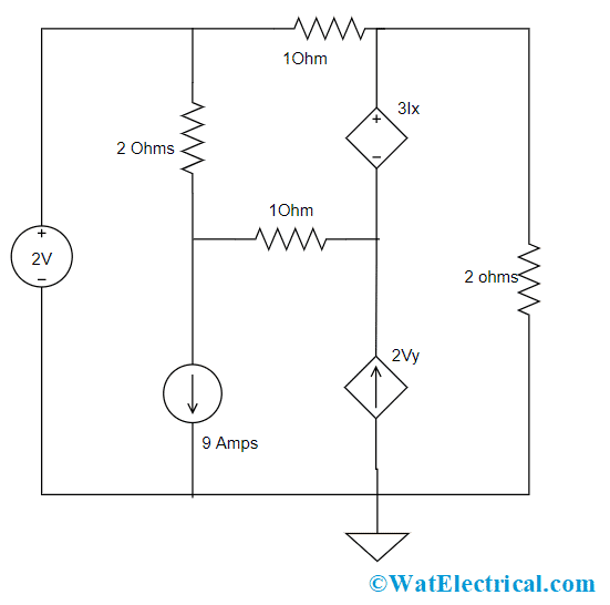
Nodal analysis having a dependent source happens when the circuit consists of one DC current source and two DC type voltage sources. To understand the concept, let us consider the below example:
1). To find the number of nodes present in the circuit and label them. In the given circuit, we have a total of 5 nodes and so N = 5
2). Choose one reference node and mark it as a ground node. In general, the node which is at the bottom of the circuit is chosen as a reference node because it has a connection with more elements
3). Then assign variables for every node where the voltages are not known.
Node A acts as a general node and a dependent voltage source is placed between node B and node C, so nodes B and C creates a supernode. Node D has a connection with a voltage source where the other node is considered as a reference node. The voltages of each node are represented as Va, Vb, Vc, Vd, and correspondingly.
For node D, the voltage is supplied by a 2V voltage source. As the voltage source positive end is connected to the node, the node voltage is taken as 2V.
4). When there are dependent sources in the circuit, then the equations are to be written in the form of other node voltage values. So,
The node voltage at node C is Vb + 3Ix
Where ‘Ix’ is the current across 2Ω resistor
Using Ohm’s law, the voltage at the 2Ω resistor is Vb + 3Ix = -2Ix
It has to be noted that the path of Ix is from reference to node C. As it is generally expected that the reference node acts as a negative terminal for corresponding node voltages, the voltage at node C is given by -2Ix
By solving the above equations, we have
Vb = -5Ix
Therefore, the node voltage at node C is
Vb + 3Ix = Vb – (3/5)Vb = 0.4Vb
5). In nodal analysis, the unknown values are written in the form of node voltages.
Here, Vb ≠ 2Vy, where 2Vy is the current across the dependent current source and this current is to be represented in terms of node voltages. Vy is the voltage between node D and node A. the positive end has a connection with node D and the negative end connects with node B.
So, Vy = 2 – Va.
6). Now, apply the KCL principle at every node in the circuit by making the total outflow current at the nodes to ‘zero’
At node A:
9 + (Va – Vb)/1 + (Va – 2)/2 = 0
(-3/2)Va + Vb = 8
At super node (node B and node C)
-2Vy + (Vb – Va)/1 + 0.4Vb/2 + (0.4Vb – 2)/1 = 0
-Va – 1.6Vb = 6
By solving the above two equations, we have
Va = -2 Volts and Vb = 5 Volts
So, Vy = 2-Va = 4Volts
Ix = -0.2Vb = -1.4 Amps
Difference between Nodal and Mesh Analysis
The below tabular column explains the major difference between nodal analysis and mesh analysis.
| Nodal Analysis | Mesh Analysis |
| Here, at specific nodes, the voltage values are observed | Here, at specific nodes, the current values are observed |
| Identifies independent nodes | Here, mesh loops are identified |
| Use KCL principle at independent nodes | Use KVL principle at mesh loops |
| Using Ohm’s law, KCL equations are represented in the form of node voltages | Using Ohm’s law, KVL equations are represented in the form of mesh currents |
1). How Does Nodal Analysis Work on Nonlinear Circuits?
In general, nodal analysis can be directly applied for DC linear circuits. Whereas for non-linear circuits, al the non-linear components are to be transformed into linear components, and then the nodal analysis is applied.
2). Which law is used in the nodal analysis?
In nodal analysis, Kirchhoff’s current law is used.
3). What is the advantage of nodal analysis?
Nodal analysis is applicable for both planar and non-planar circuits and this is the best technique for circuits having voltage sources.
4). What is nodal analysis in an electric circuit?
In electric circuits, nodal analysis is a technique of knowing the difference in voltage between the nodes in an electric circuit using branch currents.
5). What is the condition for nodal analysis?
The fundamental condition in the nodal analysis is that the branch currents at a specific node should be equal to ‘zero’.
6). Can you do nodal analysis with voltage sources?
Yes. The analysis of nodal analysis with a voltage source is the same as a current source.
7). What is node voltage?
Node voltage is the technique of solving simultaneous equations to know the voltage value at every node in the circuit.
know more about Kirchhoff’s Law MCQs.
Please refer to this link to know more about Biot Savart Law.
So, this is all about the concept of nodal analysis. This article has provided clear and detailed information on nodal analysis procedure, solved example, nodal analysis with current and voltage sources, supernode and its examples. Also, it is recommended to know how nodal analysis works with resistors?