In recent past, electrical systems and its generation, transmission, and distribution have occupied the more substantial part of the technology, administration, economic mechanism, and industry sector. The major areas of its utilization include the commercial sector, industries, transport, fishery, and so on, where higher voltage from the power generation substation and distribution systems should be converted to device rating voltages. It involves increased complexity and several wear and tear devices. In scenarios where both domestic and industries are in a single community, the distributed voltage has to be increased or decreased as per the electrical standards. During these instances, several devices, such as step-up transformer, step-down transformer, and potential transformers are used to reduce the voltage and transmit to the next electrical connectivity unit efficiently and safely. In this article, a brief of a potential transformer, circuit diagram & construction of a potential transformer, working principle, types of voltage or potential transformers, errors, and its applications are discussed along with its respective pictorial diagrams.
What is the Potential Transformer?
Definition: A Potential transformer, also known as a voltage transformer, is a static electrical device used in an electrical power system for decreasing the voltage as per the system ratings, meters, and relays. The requirement of decrementing the input voltage will lead to the safe utilization of commercially available relays and meters used for protection and metering, which are designed for low voltage.
Working Principle
The working principle of a potential transformer mainly depends on mutual induction. The primary and secondary winding of the transformer are electrically insulated from each other but magnetically interconnected through the minimal reluctance path of the core. The transformer’s primary winding is connected to the input voltage, results in alternating flux generating in the laminated core. As per Faraday’s law, the flux linkage across primary winding induces EMF across the secondary coil, and current starts to flow through the load.
Thus, Faraday’s law is proportional to core properties and high magnetic permeability. The equations to calculate permeability and flux induced inside the circuit are as follows,
∅=N*I—– (1)
Where ∅ = Induced flux
N = Number of turns
I = current flowing through the circuit
∅ ∝ A/L—- (2)
∅ = Measured Flux in the core
A = Potential transformer cross-sectional area
L = Flux path length of the core
R=l/μA —-(3)
Where R = Reluctance
μ = Permeability of the core material
The above equation (3) shows that the value of reluctance increases with an increase in the magnetic path and reduces with an increase in core cross-sectional area and permeability.
Construction of Potential Transformer
The potential transformer is designed and manufactured using the top-class core materials with minimal flux density. This helps to achieve low magnetizing current. The end-points of the transformer are the core unit of the actual model and designed in such a way that phase shift between output and input voltage is minimal, and variations amongst load and voltage ratio are less.
The secondary winding comprises less transformer turns, whereas a large number of turns at the primary side. The co-axial winding of the potential transformer reduces the leakage reactance. Additionally, by diving, the primary winding into major sections reduces the installation cost and insulation amongst layers.
Circuit Diagram of Potential Transformer
Since the test circuit output is calculated in terms of the voltage pulse, the potential transformer is connected in parallel with the primary circuit. The operating principle is similar to that of a step-down transformer. The input phase and ground are connected to the primary winding of the transformer.
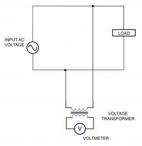
circuit-diagram-of-potential-transformer
The output of the second potential terminals is calculated using numerous measurement tools such as wattmeter and voltmeter. Similar to a step-down transformer, the high AC voltage is applied across the primary winding, and induced low voltage is observed across secondary windings. The secondary and primary winding of the transformer is coupled using a magnetic coupling principle.
The types of potential transformers are categorized into two types, namely, the conventional wound types (electromagnetic types) and the capacitor voltage potential transformers. In comparison to the latter, the former (capacitor voltage potential transformers) are wound type and expensive due to the additional insulation requirement. The capacitive potential transformer encompasses a magnetic potential transformer and a capacitive type potential divider circuit.
Errors in Potential Transformer
The below-mentioned figure depicts the phasor diagram of a potential transformer.
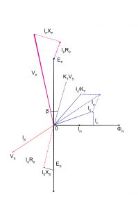
phasor-diagram-of-potential-transformer
The keywords are as follows,
Is= Secondary current
Es= EMF across the secondary winding
Vs = Voltage across the secondary terminal
Rs= Resistance across secondary winding Xs– secondary winding reactance
Ip= Primary current
Ep= Induced EMF across primarily winding
Vp= Primary terminal voltage
Rp= Resistance across the primary winding
Xp= Reactance across the primary winding
Kt= Turn ratio
Io= Excitation current
Im= I0 magnetizing component
Iw= Io core loss component
Φm= Main flux
β = Phase angle error
The main flux (φm) is considered as a reference signal. The excitation current Io and reversal secondary current Is with a multiplication ratio of 1/kt defines primary current. Let Vp be the primary terminal voltage of the potential transformer.
The values of IpXp and IpRpdepicts the primary winding voltage drop due to resistance and reactance. The primary induced EMF across terminals can be calculated by subtracting the voltage drop to the primary voltage.
The mutual induction generated due to the transformation of primary EMF to the secondary winding captures the value of secondary induced emf. The effect of secondary winding resistance and reactance results in the secondary output voltage across the secondary terminal.
The ratio error or voltage error of the potential transformer is the difference between the actual value and the ideal value(Vp/Kt ). It is expressed as,
Voltage error (%)= (VP – KT *VS )/VP * 100% —– (4)
At the initial stage, the internal impedance across the primary winding develops the voltage drop. In the later stages, it is transformed into secondary winding through turns ratio. There again causes a voltage drop due to secondary winding impedance. These are the significant reasons for the voltage drop across the transformer.
Applications
The applications of potential transformer include the following
- Potential transformers are deployed in metering devices for measuring energy billing and other calculation purposes.
- It is used as a protection control device that can be of system protection or protective relaying
purposes. - It is used as a load survey tool for measuring industrial loads and its economic management.
- In power grid as a voltage synchronizing devices
Please refer to this link to know more about Instrument Transformer MCQs, Dynamometer Type Wattmeter MCQs.
Thus, this is all about an overview of a potential transformer like working principle, construction, circuit diagram, and its applications. Here is a question for you, what are the advantages of potential transformer?