Switched reluctance motor is an electromechanical energy conversion device, which converts electrical energy to mechanical energy. As compared to DC motor where energy conversion takes place due to Lorentz Force Law, in switched reluctance motor the energy conversion takes place due to principles of variable reluctance. Reluctance is defined as the opposition to flow to the magnetic field. Its electrical equivalent is the resistance which opposes the flow of current. In the magnetic field, we define the flow of the magnetic field as flux, but whereas in the electrical field the flow of charges is defined as current. Due to the property of the magnetic field, magnetic poles are formed on the stator and rotor of the reluctance motor. Interaction between these poles causes the motor to rotate. For varying the magnetic poles, switching circuits using power electronic devices are used. Because of this, the term switched has been used.
What is Switched Reluctance Motor?
Definition: It’s a single phase electromechanical energy conversion device, which converts electrical to mechanical energy. The electromagnetic torque that is produced in a reluctance motor is due to the principle of variable reluctance. To obtain a variable reluctance, the poles must the excited with opposite charges, i.e, if one pole of the stator is south, next instant, it should be north. Such that this variable field will create a variable torque for the rotor to rotate. For the creation of a variable field, a switching circuit is used using power electronic devices. The switching circuits are triggered such that, a rotating magnetic field is created on stator poles.

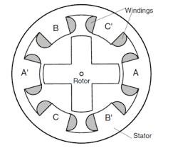
Switched Reluctance Motor
As shown in the figure, the outer part is stator poles and the inner parts are rotor poles. The stator poles are excited by a single-phase supply. For the case of synchronous reluctance motor, squirrel cage rotors are used for the creation of a rotating magnetic field. Since single-phase, supply cannot produce a rotating magnetic field. In the case of a switched reluctance motor, the rotating field is produced with the help of power electronics-based switching circuits.
According to the reluctance principle, the magnetic flux always tries to flow through the minimum reluctance path, just as the current tries to flow in the minimum resistance path. Hence the reluctance between the stator poles and rotor poles is varied, and the rotor tries to align itself in the minimum reluctance axis. In this process, a variable reluctance torque is produced, which rotates the rotor.
Switched Reluctance Motor Design
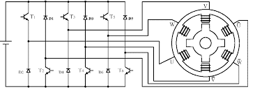
The following figure has shown the design of a three-phase switched reluctance motor. It is fed by a DC source, which is converted to AC by a three-phase inverter. Each leg of the inverter consists of two switching devices such as MOSFET or IGBT. Each phase of the stator is connected to one phase of the inverters. It is 3 phase inverter that converts DC to AC based on the triggering of the switches.

Switched reluctance motor design
The switches are numbered as per the switching sequence. The upper half of the circuit consist of switches 1,3, and 5. The lower half the circuit consists of switches 2, 4, and 6. The switches 1 and 2 i.e. each switch from the upper half and lower half at a time are triggered and these two forms one phase. Those two switches are connected to two poles on the stator. Similarly, 3,4 and 5,6 form the remaining phase and are connected to the other poles of the stator.
Working Principle
The switched reluctance motor working principle is fundamentally the action of the rotor to form a minimum reluctance path. When the three-phase supply is given to the stator, it creates a rotating magnetic field in the stator. The rotating magnetic field rotates at the speed of synchronous speed given by (120*f/P). Where f is the frequency of supply voltage, and P is the number of poles. Once a three-phase supply rotating magnetic field is produced, it aligns with the rotor circuit to form a variable torque.
The three-phase supply is obtained from the inverter switching circuit. It can be noted that each device or switch conducts for 120 degrees and each switch is triggered at a delay of 60 degrees. Further, no two switches in the same are triggered at the same time, which will short circuit the source. Once a three-phase supply is formed and fed to the stator, the rotor tries to align itself to the rotating three-phase magnetic field and starts rotating. This is called variable torque.
Switched Reluctance Motor Construction
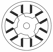
Constructionally, a switched reluctance motor consists of two parts, one is the machinery part and the other is the switching circuit. In the machinery part, the machine like a DC motor consists of stator poles and rotor poles. The stator poles are made up of silicon steel.

Switched Reluctance motor construction
The poles are projected outside. The number of poles depends on the speed of the machines. Generally, we have 6 poles for speed near 1000 rpm. The rotor winding is usually made of ferromagnetic materials. Ferromagnetic materials have the least reluctance and higher coefficient of susceptance. Since the rotor has to rotate in magnetic field ferromagnetic materials are most suited.
Also, these materials have less amount of hysteresis and eddy current losses. The rotor is stamped into the stator structure. In some cases, hall-effect based sensors are used to identify the position of the rotor dynamically. This gives scope for speed control of the motor. The construction of the motor is simple and robust with the least maintenance. It provides overall high efficient operation and speed control of the motor also becomes easy. Due to these reasons, reluctance motors are one of the highly used motors.
Characteristics
The characteristics of the switched reluctance motor can be summarised as
- It may be a single-phase or 3 phase reluctance motor
- Speed control is easy.
- High speed can be achieved with the modification of triggering circuits.
- By the use of inverter, it can be operated with DC supply also.
- Control of one phase is independent of the other two phases.
- The unutilized energy fed to the motor can be retrieved by using the feedback diodes. This improves efficiency.
- Different speeds can be obtained by varying the firing angle of the switching devices.
Advantages
- The advantages of a switched reluctance motor include the following.
- This motor is more efficient as compared to a DC motor, as the unused energy can be fed back to the source using the feedback diodes.
- The speed control of this motor is easy as the supply phases can be varied to a large extent, and a smooth variation of speed can be obtained.
- The motor can be excited with a DC supply or with an AC supply also.
- Due to the robust nature of stator poles, the maintenance is less.
- The voltage rating of the switches is also less which makes the machine affordable.
Disadvantages of Switched Reluctance Motor
The disadvantages of the motor are as follows
- The main disadvantage is there is the presence of ripple torque in the machine. The ripple torque is caused due to unwanted interferences between the rotor and stator magnetic fields also called harmonics. The harmonics cause ripple torque and unwanted losses. However, it can be overcome either by using advanced modulation techniques such as pulse width modulation or space vector modulation. Filters are also used.
- Due to the presence of switches, they often get wear and tear problems. So we need to replace them periodically. But due to their less cost, it won’t hamper the system efficiency.
- The switching losses also degrade efficiency. Usually, the switches have high switching losses and low conduction losses.
Know more about Single Phase Induction Motor.
Please refer to this link to know more about Switched Reluctance Motor MCQs.
Applications
Due to its versatility, switched reluctance motors are often used in
- Robotics
- Aviation
- Industrial Applications
- Automation
- Washing machines
- Vacuum cleaners
- Fans
Know more about Limit Switch MCQs, Reluctance Motor MCQs.
We have seen the principle and operation of switched reluctance motors. Due to the advent of power electronic devices, these motors have gained popularity. However, due to dependence on switching devices, they have some limitations. The use of hall-effect based sensors also improves the operation. It would be interesting to think about how to control the speed of the switched reluctance motor in a closed-loop circuit? Which controller would give a more efficient performance?