In the previous article, we have discussed the DC generator which works on Faraday’s law of electromagnetic induction. Similarly, the asynchronous motor also works on the same principle but the only difference is, this generator gives a 3-phase AC output voltage from stator windings whereas the DC generator gives the output like a DC or a single DC. The first synchronous generator was used in the year 1870 when the arc lamp was invented by P.N. Jablochkov which is named the Jablochkov candle.
What is Synchronous Generator?
Definition: A synchronous machine that works like a generator is known as a synchronous generator and also called an alternator. The main function of this generator is to generate commercial frequency current frequently by converting the mechanical energy from the main mover to an AC electrical energy at a specific frequency & voltage. These generators are used in the power industry in thermal power, hydropower, and generation of power in nuclear & diesel.

synchronous-generator
These generators are applicable for changeable speed wind turbine applications because of less revolving synchronous speeds. At a grid frequency, they generate the voltage and they don’t require a pitch control machine. This machine will increase the turbine cost and makes pressure on the generator as well as the turbine. The operation of these generators in changeable speed will produce variable frequency power as well as variable voltage.
Construction
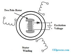
The construction of a synchronous generator is shown below. The main parts of this motor mainly include a stator as well as a rotor. But in most of these generators, field exciters revolve and the armature coil will be immobile.

synchronous-generator-construction
a). Stator
Not like in the DC machine, the stator of this generator is not used to serve lane for magnetic flux. As an alternative, the stator is utilized to hold armature winding. The stator core can be designed with a magnetic iron otherwise steel alloys lamination to reduce the eddy current losses
- In synchronous generator, armature winding is stationary because of simple immobile armature winding insulation at high voltages, which may be high like 30 kV or above.
- The output of high voltage is directly received from the motionless armature whereas, for a rotating armature, there is a huge brush contact drop at high voltages, and also the flashing at the surface of the brush will occur.
- Field exciter winding can be arranged within a rotor as well as the low DC voltage is transmitted securely.
- The armature winding can be braced well, so as to prevent deformation caused by the high centrifugal force.
b). Rotor
In the synchronous generator, there are two kinds of rotors used namely Salient type and cylindrical type.
- Salient pole rotor can be used in alternators with low & medium speed. In type, it includes a large number of salient poles attached to a magnetic wheel. These are covered to reduce the eddy current losses. These rotors have large diameters and short wavelengths.
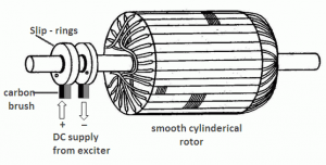
- Cylindrical rotors are mainly used in high-speed alternators like turbo-alternators. This rotor includes a flat as well as a solid steel cylinder with slots and an external periphery. These slots consist of field windings.
Working Principle
The synchronous generator working principle is the same as a DC generator. It uses Faraday’s law of electromagnetic induction. This law states that when the flow of current is induced within the conductor in a magnetic field then there will be a relative motion among the conductor as well as the magnetic field.
In synchronous generator, the magnetic field is immobile & conductors will rotate. However, in practical construction, armature conductors are motionless & field magnets will rotate between them.
The rotor in the synchronous generator can be fixed mechanically toward the shaft to turn at synchronous speed (Ns) under some mechanical force which consequences in magnetic flux cutting in the stationary armature conductors of the stator. Due to this direct flux cutting result, an induced e.m.f and flow of current will be there in armature conductors. For each winding, there will be a current flow in the first half cycle after that in the second half cycle with a specific time lag of 120°.
E.M.F Equation of Synchronous Generator
The e.m.f equation of this generator is shown below.
Eph = 4.44 Kc KdΦfTph Volts
Where,
‘P’ is poles
‘ϕ’ is Flux for each pole in Webers
‘N’ is the speed in rpm (revolution per minute)
‘f’ is the frequency in Hz
‘Tph’ is the number of turns connected in series per phase
‘Kc’ is the span factor of the coil
‘Kd’ is the distribution factor of the coil
Synchronous Generator Characteristics
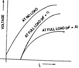
Synchronous generator load characteristics are shown below. When the speed and exciting current are constant, then the thermal voltage will be changed along with the load current within the armature. The load characteristics can be defined as the main relationship between the load current & the thermal voltage of the synchronous generator.

synchronous-generator-characteristics
As the armature current rises, then the terminal voltage falls because of resistance as well as reactance in armature winding, and armature reaction.
The graphical representation of load characteristics is shown below.
Excitation
The synchronous generator excitation can be defined as the assembly of flux through flowing current within the field winding. The excitation system is the system that is used for the excitation of the synchronous system. Direct current is necessary for exciting the field winding of the rotor within the machine. DC supply can be given to the field of the rotor in the tiny machine through a DC generator known as Exciter. A mini DC generator like a pilot generator provides the supply to the exciter. Both the exciter & pilot exciter are placed on the main shaft of the generator.
The main exciter’s DC output can be provided to the field winding in the machine through slip rings & brushes. In small generators, the pilot exciter is eliminated.
Applications of Synchronous Generator
The applications of synchronous generator include the following.
- It is used in the systems wherever stable speed is necessary.
- It is used to preserve the power factor (PF) of the system.
- It is used in power generation plants because of stable frequency.
Please refer to this link to know more about Synchronous Generator MCQs.
Thus, this is all about an overview of the alternator or synchronous generator. An alternate name of this generator is an alternator and the main function of this is to change the power from mechanical to electrical. The electrical supply which is used in homes is mostly generated through this generator. Here is a question for you, what are the advantages of the synchronous generator?