An electrical generator is a machine that converts mechanical energy into electrical energy. Based on its operation, it is classified as AC and DC generator. An AC generator is more advantageous compared to a DC generator. Because in DC generator, the usage of commutator brush drop will be more and the operation will not be smoother. So, the AC generator is used for smoother operations. This AC generator itself is called an Alternator which finds its usage most common in the automobiles. Earlier, DC generators are used in the automobiles as a dynamo to generate energy while the vehicle is in running conditions. But, because of the advantages of AC generators over DC generators, these are used for the generation of energy for its continuous operation while running. In this article, we shall discuss what is an Alternator, construction, working, types, emf equation, parallel operation, and applications.
What is an Alternator?
Definition: It is a machine that converts the input mechanical power into an output alternating electrical energy. It works just like a generator. Hence, it is also called as AC generator.
Construction
It consists of a Yoke, pole core, stator, rotor, armature, slip rings, bearings, and fan. The yoke is the outer portion of it is used as a protecting cote for the machine. It protects against the environmental conditions such that the inner parts do not get damaged. It also gives mechanical support to the machine as well. Pole core is consists of pole shoe that gives support for the windings to rest on the pole shoe. The entire winding and pole shoe are considered as the pole core. The stator is the stationary part on which armature winding is wound. The rotor is the rotating part of the machine on which the field winding is wound. The clear view of the machine is shown in the figure below.
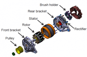
Parts of the machine
The armature core consists of armature windings, slip rings, and brushes. The armature develops armature current when the coil cuts the magnetic flux such that an armature flux is also developed. The slips rings are responsible for the smoother operation between the brushes in order to avoid twisting of the winding. The brushes are used for the collection of current from the slip rings. The bearings are employed for the operation to be performed smoother. A fan is employed is to exhaust the heat that is generated during the running conditions.
The constructional diagram of the machine is shown in the figure below.
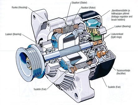
Automotive Machine
Working
It works on the principle of faradays law of electromagnetic Induction. Any rotating machine when rotated in the magnetic flux works according to this principle.
The working of this machine is similar to that of an AC generator. The working figure of an AC generator is shown in the figure below.
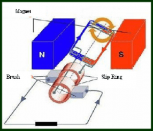
Working Principle of the AC generator
Armature winding is a collection of coils placed in the magnetic field. The coil when rotated in the magnetic field by a prime mover, it cuts the magnetic lines of forces thus, generating an induced emf. This generated induced emf is according to the principle of faradays law of electromagnetic Induction. The induced emf develops current to flow in the armature winding. The direction of the armature current is found by using the Flemings right-hand rule.
The induced emf will be zero when the coil is in the alignment of magnets and is maximum when the coil is perpendicular. As the coil is rotated the current changes continuously which can be observed in a galvanometer. The current is passed through the slip rings and then to the brushes. The slip rings are used for the smoother operation of the machine and brushes are used to collect the current from the slip rings and deliver to the load. The coil movement in the magnetic field at different points is shown in the figure below.
EMF Equation of Alternator
The flux linkages in this machine is given by
Ф = flux per pole Induced emf e = -T dΨ/ dt
=- T d/dt (Фcosωt)
= T Фωsinωt
= TФ. 2πf. sinωt
= 2πfTФ.sinωt
Emax = 2πfTФ
= Emaxsinωt
= Emax.cos(ωt-90°)
Erms = Emax / √2 = √2πФfT = 4.44 ФfT
Therefore, E = 4.44 ФfT
The emf equation of this machine is given by E = 4.44 ФfT
Types of Alternator
Based on the construction of the rotor this machine is classified as
- Salient Pole Type, and
- Cylindrical Pole Type.
Salient Pole Type
It consists of a more number of poles so, rotor diameter is large. It has a larger diameter and a smaller axial length. the prime movers or turbines used are of low speed such as hydraulic turbines like Pelton wheel, Kaplan, and Francis turbines. It is used for low and medium speed applications. These are used in hydropower stations and diesel power stations. These are also called as Hydro Alternators. The salient pole rotor type figure is shown in the figure below.
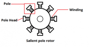
Salient Pole Rotor
Cylindrical Pole Type
The number of poles used here is either 2 or 4. As the poles used are minimum, the rotor diameter is small and the axial length is larger. The speed of this type ranges between 1500-3000 rpm. The turbines or prime movers used here are of high speed such as the steam and gas turbine. These are used in steam power stations and gas power stations. The cylindrical rotor type machine is shown in the figure below.
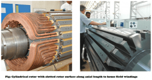
Cylindrical Rotor
Difference between a Generator and an Alternator
- A Generator is a machine that converts mechanical energy into electrical energy. It is of two types I,e AC and DC generators. DC generator converts the ME to unidirectional EE whereas the AC generator converts the ME to an alternating EE. An AC generator is classified as a synchronous generator and an Induction generator.
- It is also a type of generator that converts the input mechanical energy into an output alternating electrical energy. It rotates at the synchronous speed I,e Nr = Ns and constant frequency. Simply, it is an AC generator that is used commonly in automotive. It is also suitable for conventional energy power station I,e thermal, nuclear, hydro and gas power stations.
Parallel Operation of Alternator
Conditions for Parallel Operation
- The terminal voltage of the incoming machine should be the same as of the existing system. If not circulating currents flow between the two systems. It is adjusted by varying the field excitation and can be verified by observing the voltage across the systems by installing a voltmeter. If the voltmeter indicates zero, then we can say that the two systems are at the same voltage levels.
- The frequency of the incoming machine should be the same as of the existing system. If not circulating currents flow between the two systems. It is adjusted by varying the speed of the prime mover and can be verified by observing the vector potential difference.
- The phase sequence of both the machines (incoming and the existing alternator) must be the same if not circulating currents will flow arise in the two systems.
Uses of Alternator
- It is commonly used in automobiles.
- It is used in conventional energy power stations like thermal, nuclear, hydro and gas power stations.
- Used in Diesel engines.
Picture Credit
Thus, in this article, we had an overview of what is an alternator. It is an AC generator and similar to that of a synchronous generator. It converts the input mechanical energy into the output of alternating electrical energy. Apart from this, we had also studied the construction, working, types, emf equation, parallel operating conditions, and its applications. Here is a question for the readers, is there any difference between an AC generator and synchronous generator?
Leave a Reply