At present, the power generation landscape as well as the energy market is growing, so controlling the power flow capacity is very important. So phase shifting transformer is an essential component used to enhance AC network efficiency, protect HV equipment & transmission lines from thermal overload, enhance transmission system stability & control the flow of power between various networks. Compared to fixed power transformers, these are extremely complex power transformers with a number of windings, tap changers & a large no. of connections between the 3-phases. So this article gives brief information on phase shifting transformer theory – working with applications.
What is Phase Shifting Transformer?
A special kind of transformer that is used to control real or active power flowing throughout a multi-network power system is known as a phase-shifting transformer. This transformer is very helpful in stabilizing the flow of power & balances the loads within the power system.
This kind of transformer simply provides a phase-shifted o/p power using the i/p power with a preferred angle. The phase of the o/p quantity can be changed continuously by maintaining the magnitude stable. PSTs are the most significant components which help in enhancing AC network efficiency.
These are extremely specialized devices that need leading-edge design & manufacturing skills combined with severe quality control. As compared to traditional power transformers, these transformers are extremely complex including additional windings, tap changers & a huge number of connections between the 3-phases.
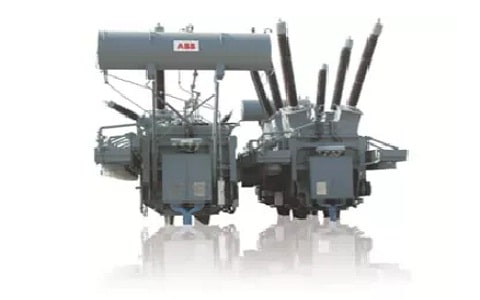
Phase Shifting Transformer
Working Principle
The working principle of a Phase shifting transformer is to control the power supply within electrical power systems. Once power supplies in between two systems, then there is a voltage drop as well as a phase angle shift between the power source & the load that depends on the power factor & magnitude of the load current. So, if the two systems are simply connected together within two or above parallel paths then a loop exists and any variation within the impedances can cause unstable line loading.
Phase Shifting Transformer Design
The phase shifting transformer design is similar to the induction motor which includes stator winding & rotor winding where the stator is kept stationary and the rotor is movable. In the following transformer design, the stator is wounded with 1-phase or 3-phase windings. The stator windings are arranged on the stator slots coated with silicon steel to decrease iron losses.
Generally, single-phase induction motors are not self-starting type motors because a single-phase supply doesn’t generate a rotary magnetic field. The transformer’s single-phase winding is split into two windings as shown below.
Phase Shifting Transformer Construction
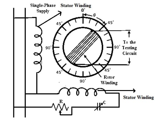
To generate a rotary magnetic field from two-phase stator winding, there should be a phase difference within the generated magnetic field. So for this reason, a phase-splitting device is utilized for generating a rotary magnetic field.
As shown in the above diagram, the two windings are arranged perpendicular to each other where one of the stator winding is simply connected through a phase splitting device & the other one is connected directly to the supply.
The phase-splitting device is the combination of a variable resistor & capacitor which are connected in series. The phase splitter’s resistance & capacitance are simply adjusted till the winding is connected and it generates a current which is displaced at 90° from other winding.
Thus, once the current within the two stator windings is displaced at 90° then it generates a uniform rotating magnetic field through the two-phase stator winding. The rotor winding is wound on a laminated structure similar to the stator. To reduce leakage reactance, the rotor winding is kept closer to the stator winding. So, there exists a phase displacement within the induced emf based on the rotation of the rotor. Here, the induced e.m.f’s phase shift is directly proportional to the preferred angle at which point the rotor is turned.
At the top of the rotor, the pointer is connected over the scale which indicates the angle by which the rotor is turned. This scale includes phase displacement angles so that the necessary phase shift from the o/p can be obtained.
Operation of Phase Shifting Transformer
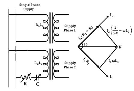
Whenever 1-ɸ supply is provided to the 2- ɸ stator winding which is displaced at 90 degrees then it generates a uniform rotating magnetic field & connects with the rotor conductors. The two-phase stator winding circuit with variable resistance & capacitance with a phasor diagram is shown below. So this type of connection is known as a quadrature winding arrangement.
Phase Shifting Transformer Working
Once the current generated by the 2-phase stator winding is displaced at 90°, then we have I2 = ji1,
V/(R2+R) + j (wL2-1/wc) = jV/R1+jwL1
R1+jwL1 = j[(R2+R) + j(wL2-1/wC)]
R1+jwL1 = j(R2+R) – j^2(wL2-1/wC)
We know that j^2 = -1, so
R1+jwL1 = j(R2+R) – (wL2-1/wC)
When real & imaginary parts are equated then
R1+wL2= 1/wc
wL1-R2 = R
Thus, by varying R and C, the required phase splitting can be attained to generate RMF. So, rotor induced e.m.f because of one stator winding can be given as;
e1 = K I sin ωt cos θ
The induced e.m.f of rotor because of stator winding where the phase splitter is connected,
e2 = K I sin (ωt + 90°) cos (θ + 90°)
= – K I cos ωt sin t
The induced net e.m.f within the rotor can be given as
e = e1 + e2
Substitute the e1 & e2 values in the above equation then we can get
= K I sinωt cosθ – K I cosωt sinθ => K I [sinωt cosθ – cosωt sinθ]
Therefore, e = K I sin (ωt – θ)
According to the required displacement of the rotor, uneven phase shift from the rotor o/p quantities can be attained. So, it can be seen that the winding of the rotor is connected in such a way that change within the phase shift doesn’t have an effect on the induced e.m.f’s magnitude & the phase shift mainly depends on the position of a rotor that is., θ.
Like a 1-phase shifting transformer, the 3-phase shifting transformer is used where there is a 3-phase supply availability is there. As compared to the single-phase type, 3-phase shifting transformers are less responsive to changes within the frequency. So the 3-phase shifting transformer output is phase-shifted without varying the voltage ratio.
Once the 3-phase supply is given to the phase shift transformer, by turning the rotor through the preferred angle then a phase-shifted o/p can be achieved without varying magnitude.
Advantages
The advantages of a phase-shifting transformer include the following.
- Phase-shifting transformers enhance grid reliability & operating performance.
- These transformers conserve energy by simply optimizing losses within the electrical system.
- These are not expensive as compared to most FACTS devices.
- These are reliable and long-lasting.
- These transformers protect transmission lines.
- It protects from thermal overload.
- Transmission system strength can be improved.
- These are robust, simple & reliable technology.
- Preventive & curative control strategies can be implemented by using these transformers for the controllability of power flow.
Applications
The applications of phase-shifting transformers include the following.
- Phase-shifting transformers or PSTs are used to transmit a phase-shifted o/p power with a preferred angle using the input power.
- These transformers are used to control active power flow.
- These transformers allow the grid operator to control sudden loop flows, so allowing the existing system to be utilized more powerfully.
- These are the most reliable as well as economical approaches to system design & power flow management.
- By using these transformers, the accessible transmission lines are loaded equally to the thermal limit without being overloaded. So, the asset within new transmission lines can be even avoided or postponed.
- The phase-shifting transformer is used for controlling power flow between two grids.
- These transformers do not enhance the transmission lines’ capacity, although if some transmission lines are overloaded when capacity is still accessible on others parallel to them, then power flow optimization with these transformers can enhance the overall capacity of the grid.
- These are useful in controlling the power flow between two large independent power systems.
- For changing the effectual phase displacement in between the input & output voltages of a transmission line, so controlling the flow of active power within the transmission line.
- It protects from thermal overload & also improves the stability of the transmission system.
Know more about Z-transform MCQs, Laplace transform MCQs.
Know more about Efficiency of Transformer, Single Phase Transformer.
Thus, this is all about an overview of a phase-shifting transformer – working with applications. This type of transformer simply provides a phase-shifted o/p power with a preferred angle using the i/p power. So, the phase of the o/p quantity is changed continuously by maintaining the magnitude stability. Here is a question for you, what is the function of a transformer?