In the domain of electronics, a feedback amplifier is a component that acts in response to minimal voltage, power, and current signals and gives the output as a larger signal which comprises the crucial waveform characteristics of the input wave. These amplifiers exist in multiple forms which are extensively implemented in many electronic devices like televisions, computers, radio, and audio equipment.
The functionality of amplification can be offered by devices such as generators and transformers whereas many electronic systems now use small circuits named amplifiers. Amplifiers are fabricated with many transistors and other devices on a single IC. This article discusses one of the most employed types of amplifiers called “Feedback Amplifier”, its principle, types, and applications.
What is Feedback Amplifier?
Feedback amplifier definition is stated in the way that this is an amplifier that has a feedback connection in between the output and input. It consists of a feedback factor in between the applied input signal and an output feedback signal. In a simple way, it can be defined like this is the amplifier where some portion of the output signal is connected to the input signal. Below is the picture which shows how feedback implementation is done and its block diagram.
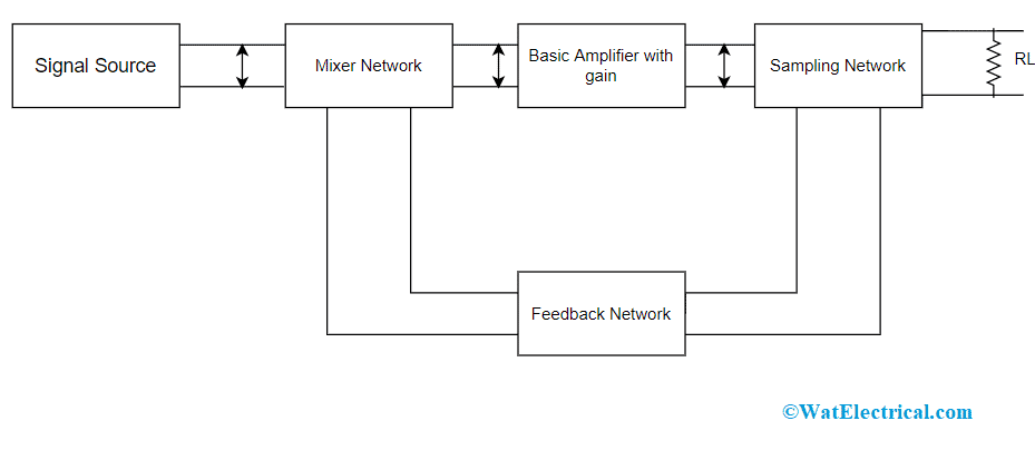
Block Diagram of Feedback Amplifier
The various sections in the block diagram of a feedback amplifier are:
Voltage Source – Here, the signal source can be either voltage or current. If the input is voltage, it is in series connection with Rs whereas for a current source it is in parallel connection with Rs.
Feedback System – This is a linear two-port system that includes resistors, capacitors, and inductors. The operation of this device is to establish a feedback connection between output and input.
Sampling Network – Sampling network is of two kinds which are current and voltage sampling systems. The output voltage gets sampled when the feedback connection is established either in a series or parallel way with the output.
Mixer Circuit – This is also termed a comparator and this can be a shunt or series mixer. This is used for mixing the input and feedback signals and then generates either positive or negative feedback for the circuit.
As the main functionality of the amplifier is to amplify the signal, an ideal amplifier consists of few crucial features such as input and output impedance, voltage gain, bandwidth, and others. All these characteristics are regulated through a feedback network and thus because feedback network is implemented in an amplifier to control many factors in the device.
Principle
A feedback amplifier mostly consists of two sections which are feedback system and amplifier. The feedback circuitry consists of resistors and the operation of this device can be known through the below explanation.
In the below picture, the amplifier gain is signified as ‘A’. This gain is defined as the ratio between output and input voltages and the feedback network isolates a voltage of βV0 from the amplifier’s output. This isolated voltage is connected as feedback to the input signal and the equation that represents this phenomenon is given as
Vi = Vs + Vf
Vo = Vs + βV0
Consider the scenario of negative feedback. Here, the output voltage equals the input voltage and then multiplied by the amplifier’s gain. So,
(Vs + βV0)A = V0
AVs = V0(1 + Aβ)
This implies
V0/Vs = A/(1 + Aβ)
This ratio of output and input voltage is termed as entire amplifier gain which is represented as Af. So,
Af = A/(1 + Aβ)
This is the principle equation of the feedback amplifier which is used for calculating the gain.
Types of Feedback Amplifier
Implementing feedback in the circuit, reduces the level of noise and enhances the amplifier functionality stability. Based on whether the feedback signal helps or contradicts the input signal, the feedback types are mainly of two kinds.
Positive Feedback
This is the feedback connection where the feedback energy (voltage or current) acts in a similar phase with the applied input signal is called positive feedback and the amplifier is termed as positive feedback amplifier. Here, the input and feedback signals create a phase shift of 1800 which results in 3600 phase shift all across the loop and this makes feedback and input signals to be in phase.
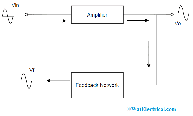
Positive Feedback
This type of feedback has the advantage of increasing the amplifier gain, whereas the drawbacks here are increased distortion levels and poor stability. Due to these drawbacks, this feedback connection is not widely used in amplifiers. And when the +ve feedback is more, this causes oscillations.
Negative Feedback
This is the feedback connection where the feedback energy (voltage or current) acts in a dissimilar phase with the applied input signal is called negative feedback and the amplifier is termed as negative feedback amplifier. Here, the input and feedback signals create a phase shift of 1800 which results in 00 phase shift all across the loop and this makes feedback and input signals to be out of phase.
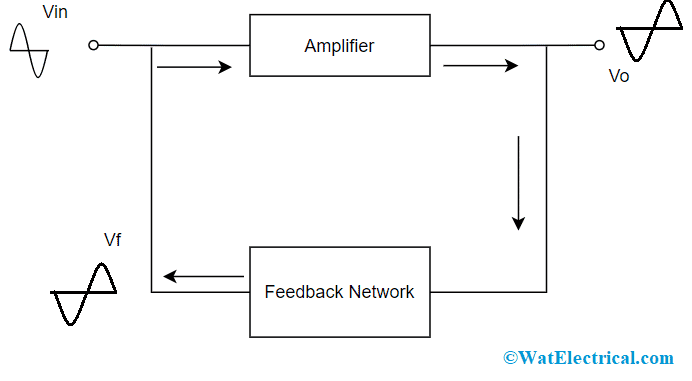
Negative Feedback
Though the negative feedback is reduced, there are many benefits of this feedback connection which are noise reduction, minimal distortion levels, enhanced stability, and increment in the range of uniform application. Because of these benefits, the negative feedback connection is utilized in many amplifies.
Feedback Amplifier Topologies
In the previous sections, it was discussed that how feedback connection is implemented in positive and negative amplifiers. Whereas the approach to how the output signal is calculated and fed to the input circuit might differ and this leads to the introduction of basic categories of the feedback. Depending on the input signal which is amplified and the desired output, the input and outputs are termed as voltage and current. And the four classifications/topologies are
- Voltage series
- Voltage shunt
- Current series
- Current shunt
The other terminology for the above feedback types are
- Voltage series called series-shunt feedback
- Voltage shunt called shunt-shunt feedback
- Current series called series-series feedback
- Current shunt called shunt-series feedback
Voltage Series
This type of voltage series feedback amplifier functions as a voltage-voltage regulated feedback system. Here, the error voltage from the feedback network is in series connection with the input signal and the level of voltage received from the output equals the output voltage level either it is in parallel or series connection.
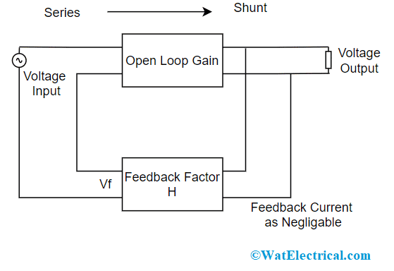
Voltage Series Topology
Using this topology, many of the inverting and non-inverting op-amps are operated where the circuit is termed as a voltage amplifier. Here, the value of ‘Rin’ is high, and ‘Rout’ is very minimal. So, this feedback configuration is considered a perfect voltage amplifier, and the transfer gain is represented as Av = Vout/Vin.
Voltage Shunt
This type of voltage shunt feedback amplifier functions as a current-voltage regulated feedback system. Here, the signal which is in feedback connection with the input signal is connected parallelly. Here, the output voltage is identified, and the current is deducted from the input current value in the shunt. This is the same in the way of currents but not in the case of voltages that are deducted.
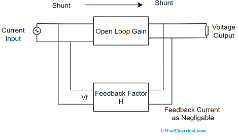
Voltage Shunt Topology
In the shunt-shunt configuration, the output voltage is fed to the input signal as a current and the shunt connections at both the terminals decrease the values of input and output impedance. So, these feedback systems functions as superlative trans-resistance systems where ‘Rin’ is very minimal, and ‘Rout’ is also very minimal where the transfer gain is Rm = Vout/Iin
Current Series
This type of current series feedback amplifier functions as a voltage-current regulated feedback system. Here, the error voltage from the feedback network is in series connection with the input signal and it is proportionate to the load current. This kind of feedback system has the ability to transform current into a voltage signal and this is connected as feedback.
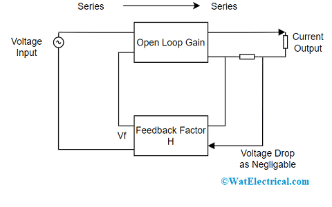
Current Series Feedback Amplifier
In the series-series configuration, the output current is fed to the input signal as a voltage and the shunt connections at both the terminals enhance the values of input and output impedance. So, these feedback systems functions as good trans-conductance amplifiers where ‘Rin’ is very minimal, and ‘Rout’ values are very large where the transfer gain is Gm = Iout/Vin
Current Shunt
This type of current shunt feedback amplifier functions as a current-current regulated feedback system. Here, the signal that is connected in the feedback way is directly proportional to the output current that flows in the load section and the feedback signal is either shunt or parallelly connected with the input signal. In this feedback configuration, the signal which has a feedback connection with the input signal is connected parallelly which is the same in the way of currents but not in the case of voltages that are added.
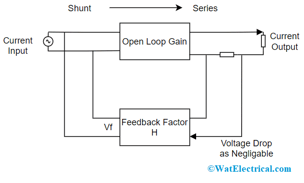
Current Shunt Topology
This type of topology does not show its impact on the system’s voltage gain because for the voltage output corresponding voltage input is needed. This current shunt configuration functions as a good current amplifier because both the input and signals are both currents and the transfer gain is Ai = Iout/Iin.
The below tabular column summarizes the input and output resistance values in all the feedback topologies.
| Feedback Topology | Input Resistance | Output Resistance |
| Voltage Series | Rin = Ri(1 + Aβ) | Rout = Ro/(1 + Aβ) |
| Voltage Shunt | Rin = Ri/1( + Aβ) | Rout = Ro(1 + Aβ) |
| Current Series | Rin = Ri(1 + Aβ) | Rout = Ro(1 + Aβ) |
| Current Shunt | Rin = Ri/(1 + Aβ) | Rout = Ro(1 + Aβ) |
Here ‘A’ corresponds to the voltage gain of the amplifier.
Applications
The applications of feedback amplifier are:
- Used in electronic amplifiers
- In the regulated power supply systems
- Implemented in amplifies those have a high range of bandwidth
This is all about the feedback amplifier, its working principle, topologies, and applications. In addition to this information, know-how two-port analysis is implemented using a feedback amplifier?