The creation of a synchronous motor took place in the year 1869 which was almost two decades back before the discovery of the induction motor. In the early stages of the 20th century, the development of induction motor happened, and its application was extensively developed. Whereas the reach of the synchronous motor was not more till the early period of the 1920s. Nearly, 5 years were needed to progress the necessary initial ability by interaction with the induction motor and also to involve synchronous motor uses for power factor modification, and ultimately to eliminate the limitation of manual initiation by the development of direct control for synchronous motors. So, this article explains one of the types of synchronous motor and it is Permanent Magnet Synchronous Motor.
What is a Permanent Magnet Synchronous Motor?
A PMSM is a type of synchronous motor which is utilized as a permanent magnet for the development of the excitation field. This is also called a brushless type of permanent sine wave motor because it generates a sine shape of flux distribution in the air gap between rotor and stator components. Even the current wave generated by this device is also in sine shape.
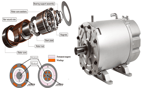
As PMSMs consist of permanent magnets, they exhibit increased torque for minimal frame size and no rotor current. These devices also have a good range of power-to-size ratio which allows for simple design having no loss in torque. There has to be commutated in the same way as BLDC motors but because of windings constriction, the signals have to be in sine shape to deliver better performance. As the PMSM devices are constructed with advanced controlling algorithms, these are mainly employed in controllers such as 32-bit PIC32MK or dsPIC33 digital signal processors or SAM microcontrollers. The permanent magnet synchronous motor diagram is shown below:

Permanent Magnet Synchronous Motor
Construction and Design
The device mainly consists of a static portion called a stator and a rotating section called a rotor. The laminations for axial air gap devices are probably generated by rolling them with soft steel strips. Different sections of the laminations are as teeth spaces where those include armature windings and the yoke section end up the magnetic path.
In general, inside the stator of the motor, a rotor is located whereas in few cases there might be rotors that are placed externally. The rotor sections consist of permanent magnets and these magnets possess high coercive forces.
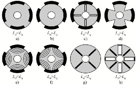
Based on the design of the rotor, synchronous motors are categorized as electric motors with and without salient pole rotors. In the electric motor with a non-salient pole rotor, the quadrature and direct inductances are equal which means Ld = Lq whereas in the motor with a salient pole rotor the inductances are not equal is Ld ≠ Lq. Below are the pictures that represent the permanent magnet synchronous motor construction and design.
Also, the PMSM is classified based on the rotor’s design which is of surface PMSM and interior PMSM. In these, the stator section is included with an external frame and a core section with windings. This type of rotor’s design is usually observed in 2-phase and 3-phase winding designs.
The other type of PMSM is based on the construction of stators which is of PMSM with distributed winding and a PMSM with a concentrated winding.
In the distributed winding, the number of slots per each pole and phase is in the sequence of Q = 2, 3…. k. Whereas in the concentrated winding, the number of slots per pole and phase is Q = 1 which means that the slots have equal spacing all through the stator perimeter. The two coils which create the winding can be either in series or parallel connection.
In addition, upon the placement of a permanent magnet on the rotor core, the PMSM is classified into two types:
Surface Mounted PMSM – Here, the magnet is placed on the surface of the rotor. As the design of this kind is not robust, it is not applicable for applications those function at high speed. As the magnet and air permeability are similar, this kind of design creates a regular air gap. So, there is no presence of reluctant torque. Ain regard to this, the dynamic efficiency of the motor is more and so it is applicable for high performed machine tool drivers and the robotics domain.
Interior/Buried PMSM – Here, the permanent magnets are placed inside the rotor other than placing on the rotor’s surface. This enhances device strength and so used for applications that operate at high speed. As because of the salience feature, there exists reluctant torque in the PMSM.
Working of Permanent Magnet Synchronous Motor
The permanent magnet synchronous motor working is dependent on how the rotor’s static magnetic field and the stator’s revolving magnetic field interact. The principle of revolving magnetic field in the stator section of the motor is similar to the 3-phase induction motor.
As per Ampere’s principle, the rotor’s magnetic field operating with the synchronous AC of the stator windings generates a torque that allows the rotor to start revolving. The permanent magnets which are located on the rotor of the motor generate a static magnetic field. When the speed of the stator field and rotor’s rotational speed synchronizes, then the rotor poles link up with the revolving magnetic field of the stator.
As per this, the PMSM device will not start automatically. It has the self-starting ability when the device has a direct connection with the 3-phase current network which means when the current frequency is in the range of 50 Hz.
EMF and Torque Equations of PMSM
The emf equation of the PMSM can be derived by using faraday’s law of electromagnetic induction. Here EMF induction in a single turn is given by
e = -N (dφ/dt)
As we consider a single turn, then N = 1
e = -(dφ/dt) ((2B lrωm sinpωmt)) Tph
= Eph sinpωmt
Where pωmt = ωe measured in radians/seconds
Then Eph = 2B lrωm Tphωm
Eph corresponds to RMS value of the phase EMF
= Eph/sqrt (2)
= sqrt (2B lrωm Tphωm)
ωm = ωe/ρ
φm = Bav τ (1) = Bav * (2πr/2ρ) * 1
The average value of the flux density for a sine wave is given by 2/π
So, φm = (2/π)B * (πr/P) *1
B * r1 = (Pφm/2)
Eph = sqrt (2B lrωm Tph. Volt)
Upon substitution
Eph = sqrt (Pφm/2) ωm Tph
Finally, the EMF equation is Eph = 4.44 fφm Tph Volt
Whereas the torque equation is
T = (3 * Eph * lph * sinᵦ)/ωm
So, this is the EMF and torque equation of a permanent magnet synchronous motor.
Direct Torque Control of Permanent Magnet Synchronous Motor
The PMSM device needs a controlling system where it might be a servo drive or variable frequency drive. There exist numerous kinds of torque controlling techniques for the control system. The selection of the technique is based on the functionality in the electric drive. The crucial techniques used for controlling a PMSM device is explained as below:
In order to resolve minor tasks, the mainly used approach is trapezoidal control using Hall sensors like computer fans. Whereas to resolve performance-related issues that arise in the electric drive, the implemented approach is trapezoidal control.
The below tabular column clearly explains the controlling techniques along with the advantages and disadvantages.
| Controlling Technique | Advantages | Disadvantages | |||
| Sinusoidal Control | Scalar | It a simple controlling schema | No optimal controlling. This is not applicable for the activities like a variable load, and loss of control is not possible | ||
|
Vector |
Field Oriented Control | Having position sensor | Extended range of controlling. It has a smooth and accurate setting for both rotor and motor position speed | It needs additional equipment of microcontroller and a rotor positioning sensor | |
| No position sensor | Extended range of controlling. It has a smooth and accurate setting for both rotor and motor position speed, but minimal when compared with the position sensor | Full speed range can be achieved only when PMSM has a salient pole rotor and also a robust controlling system is needed | |||
| Direct Torque Control | This technique has enhanced performance, extended range of control, and simple circuitry | High level of torque and current ripple | |||
| Trapezoidal Control | Open Loop | It has a simple controlling schema | No optimal controlling. This is not applicable for the activities like a variable load, and loss of control is not possible | ||
| Closed Loop | Having position sensors | It has a simple controlling schema | It needs hall sensors, and these are torque ripples. This technique is only optimal for PMSM controlling having trapezoidal back EMF and also the average torque is less than 5% | ||
| No position sensor | A robust controlling system is required | It is not applicable for low-speed operations. and these are torque ripples. This technique is only optimal for PMSM controlling having trapezoidal back EMF and also the average torque is less than 5% | |||
PMSM V/s BLDC
The difference between PMSW and BLDC include the following.
| Permanent Magnet Synchronous Motor | Brushless DC Motor |
| It is an asynchronous machine | It is an asynchronous machine |
| The input is sinusoidal currents | The device is fed with direct currents |
| This device is suitable for higher speed levels | This device is suitable for lower speed levels |
| It generates less voice | It generates high noise when compared with PMSM |
| Complicated controlling algorithms | The device can be constructed with simple controlling algorithms |
| It has the possibility of 3 phases ON at a single instance | For a BLDC, only 2 phases can be in ON state at the same time |
| Minimal core losses | It has high core losses as because of harmonic content |
This section explains the comparison between a permanent magnet synchronous motor and a brushless DC motor.
Advantages and Disadvantages of PMSM
The advantages of permanent magnet synchronous motor are:
- It has the ability to eliminate field copper losses
- Increased level of power density
- Minimal rotor inertia
- The construction of motor is robust
- Delivers enhanced efficiency
- The output is smooth torque and good dynamic performance
The disadvantages of permanent magnet synchronous motor are:
- The PMSM device is available at higher prices than other types of motors
- It has a remagnetization impact
- These are not self-starting motors
- Loss of flexibility of field flux control
Permanent Magnet Synchronous Motor Applications
The applications of PMSM are in:
- Many household appliances like washing machines, air conditioning systems, elevators, fans, and compressors
- Used in the factory automation domain
- Vacuum cleaners
- Implemented in robotic systems
- Shutters and gates
- Surveillance platforms
Know more about Asynchronous Motor.
So, this is a detailed explanation of a PMSM device. This article has provided a thorough explanation of permanent magnet synchronous motor definition, working, EMF equation, torque control, and uses. It is also important to know about what is the difference between a permanent magnet synchronous motor and other synchronous motors?

