During the period 1809, a scientist named Samuel Thomas invented the first electrolytic relay which was a part of his electrochemical telegraph development. Later on, Joseph Henry, an American inventor asserted to have a relay invention in the year 1835 which was the improvised version of the electrical telegraph that was invented in 1831. But the relay which was currently in use today was designed by Samuel Morse in the year 1840. The mechanism of this device was similar to a digital amplifier, reiterating the signal and so permitting the signal which has to be propagated to the desired distance. And now, the one most prominent type of relay which was more in implementation is Distance Relay. This article is going to explain distance relay operation, design, types, advantages, and applications.
What is Distance Relay?
Distance relay is also termed as impedance or distance protection relay where the device operation is based on the distance that is between the impedance of the defective section to the position where the relay is located. This is considered a voltage-managed device. The relay is used for the measurement of impedance at the defective location when the value of impedance is minimal than the impedance value of the relay setting. When this happens, the device alerts the circuit breaker to close the contacts bypassing the tripping command.
This distance relay persistently supervises the line current and voltage flow through PT and CT correspondingly. When the proportional voltage of voltage and current is minimal, then it indicates the relay is functioning. The distance relay diagram is shown below: As there arise more complications in power systems and fault current differs as per the variations in generation and system configuration, direct overcurrent type of relays are somewhat problematic in resolving these issues. Whereas distance relay setting is persistent across various changes outside the protected line.
This is the fundamental distance relay theory.
How Distance Relay Works?
The operational principle of this device is not so complicated when compared with other types of relays. The device consists of a voltage element that is fed from the potential transformer and a current element that is fed from the current transformer. The deflecting torque is generated by the CT’s secondary current, and the restoring torque is generated by the potential transformer’s voltage.
The distance relay principle can be explained in two conditions:
Normal Condition – Here, the restoring torque is maximum than that of deflecting torque. So, the relay will not function.
Defective Condition – Here, the current value is more when compared with voltage. Therefore,
Deflecting torque > Restoring torque
In this condition, the movable parts of the relay initiate to move until it becomes “No contact” of the relay. So, the operation of distance relay is dependent on the ratio of the system’s voltage to current. As the result of the calculated ratio is an impedance value, the device is so termed as impedance relay.
The functionality of the relay is based on the predetermined value of the ratio between voltage and current which is impedance. The device only functions when the calculated ratio is minimal than the predetermined value. So, it is stated that relay functionality takes place only when the line impedance is < predetermined impedance. When the transmission line’s impedance has a direct relation to the length, then it can be easily stated that distance relay only functions when defect takes place within the specified line length or distance.
Different Types
A distance protection relay is mainly categorized into the below types which are:
- Definite distance
- Time distance
- Admittance Relay
- Reactance Relay
Let us have a detailed analysis of each of these relays.
Definitive Distance Relay
This is a type of balance beam relay where on the end of the beam is located in a horizontal position and this is backed by a hinge and the other end of the beam is dragged downwards by the magnetic force that exists in the coil that is fed from PT connected in series to the line. The torque generated by the downward forces allows the beam to be at an equilibrium state. The torque produced because of voltage coil operates as restraining torque and the torque produced because of current coil operates as deflecting torque.
In normal condition, restraining torque > deflecting torque, so the contacts stay to be open. Whereas, if there arises any defect in the feeder, then the feeder voltage reduces, and the current value increases. This creates impedance < predetermined value. So, the current coil pulls the beam strongly than that of the voltage coil which makes the beam to tilt towards relay contacts and causes the relay to trip.
Time Distance Relay
This type of relay automatically corrects the operating time based on the relay distance from the defective position. The operation of this relay is not dependent on voltage to the current ratio which corresponds to that
Functional time α (Voltage/current) α Impedance α distance through the transmission line
This type of relay is included with a current-driven component such as a double winding type of induction overcurrent relay. The spindle which carries the disc has a connection with it through a spiral spring where it has coupled with 2nd spindle that carries the bridging component of the relay contacts. In general, the bridge is in an open position through an armature that is held in opposition to the pole face which is excited by the circuit’s voltage to safeguard it.
Admittance Relay
This is the most widely implemented type of distance relay. This is considered as a tripping relay in the case of pilot patterns and considered as a backup relay in the case of distance patterns. The feature of this device is that it crosses over origin in the R-X plot and so it is directional. While in the electromechanical structure, the plot is circular and solid-state structure, the shape of the plot represents transmission line impedance.
Reactance Relay
This relay is a straight-line featured distance relay that reacts only to the protected line’s reactance. It is non-directional and utilized as a supplement to admittance relay such as tripping relay. This makes the entire circuit’s safety to be independent of resistance. This is solely employed for short lines where the defective arc resistance is of a similar order of line length’s magnitude.
Characteristics
Few of the numerical relays calculate the fundamental defective impedance and then define whether the functionality is necessary based on the impedance boundaries plotted as in the R/X graph. Numerical and general kind of distance relays that compare the impedance components of the basic distance relays will not calculate basic impedance values.
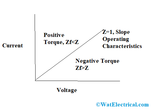
Here, we consider the relay characteristics when the device functions in operating conditions. The current flow across the current transformer is plotted on X-axis and the supply voltage by the potential transformer is plotted on Y-axis.
When the relay impedance is less than the transmission line in a defective condition, then it generates positive torque above the positive characteristic line. Similarly, when the relay impedance is greater than the transmission line in a defective condition, then it generates negative torque.
In addition to this, the distance relay functional characteristics can be explained through the R-X plane. Consider the line’s impedance is the circle’s radius where ‘X’ is the phase angle and ‘R’ is the vector position.

Characteristics
In the positive location of the circle, the line’s impedance is less than the circle’s radius and in the negative location of the circle, the line’s impedance is more than the circle’s radius. With these distance relay characteristics, it can be stated that these distance relays are mainly appropriate for high-speed transmission lines and so-called high-speed relays.
Example
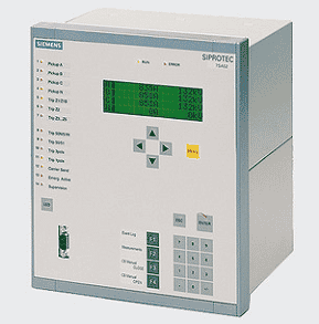
Below is the picture that shows 7SA522.

7SA522 Distance Relay
The below tabular column depicts the modern type of distance protection relay and it has activities as follows:
| ANSI Value | Pin Description | ANSI Value | Pin Description |
| 50HS | Switch onto defect safety | 27WI | Protects in week infeed |
| 50BF | Breaker failure safety | 50/51/67 | Backup for overcurrent safety |
| 59/27 | Protects in over or under voltage values | FL | Fault detector |
| 79 | Auto reclosure | 21/21N | Distance protection |
| 86 | Lockout | 85/21 | Tele protection for distance safety |
| 25 | Check for Synchro | 68/68T | Power swing tripping |
| 74TC | Checking for trip circuit | 50N/51N/67N | Directional ground fault protection |
| 81 O/U | Over or under frequency value protection | 50 STUB | STUB bus overcurrent phase |
Advantages of Distance Relay Over Overcurrent Relay
Distance relays are mostly chosen than of overcurrent relays due to the reason that these will not be easily impacted by the variations in short-circuit current magnitude whereas overcurrent relays are easily affected. So, distance relays are minimally impacted by the modifications in capacity generation and even in system configuration.
Distance Relay Testing
Testing of the relay is necessary in order to analyze the performance of the protection relay, relay configuration, testing, installation, setup, and entire analysis of the device for better protection.
As distance relays are employed for multiple applications universally, their functional condition is based on the electrical quantity’s calculation such as current, voltage, assessment of impedance value for the defect which has direct proportion to the distance that is between the relay and the location where defect happens.
The distance relay testing procedure is explained as below:
In order to initiate testing for this device, a few of the observations to be considered are:
- It has to be ensured that the 3 zones of the relay are properly arranged.
- Zone1 has to be arranged for instant tripping mode in the forward directional path.
- Zone2 to be arranged for over-reaching within the specified time gap in the forward directional path
- Zone3 to be arranged for over-reaching within the specified time gap in the double mode for the reverse directional path
Also, the kind of power system used in the 400kV transmission line of the three-phase model and the three resistive loads (where two of those are operated at 9kV) has to function at 400kV. In addition to these, the other protection functional modes have to be switched OFF during testing the device. Check whether all the PT, CT, and transmission line connections are properly arranged.
Disadvantages
The disadvantages of distance relay are:
- The device does not hold the ability to recognize whether the fault is internal or external
- The measuring ability of the defective resistance is restricted
- Changes in power swings show an impact on the performance of the device
Distance Relay Applications
The applications of impedance relay are:
- Used as both backup and primary protecting device
- Applicable in transmission lines
- Employed for protection of distribution lines in the case of high AC voltage levels
Know more about Fault Analysis MCQs, Protective Relay MCQs.
So, this article has provided clear clarification on distance relay theory, working, types, advantages, applications, and drawbacks. Also, know what are the distance relay characteristics as per impedance comparison?