The transformer rectifier, also known as the transformer rectifier unit (TRU) has versatile applications due to its robustness and efficiency. It is mostly used in the aviation industry because of its mobility and lightweight. The transformer rectifier unit combines the characteristics of a transformer and a rectifier. With the use of this unit, a variable DC voltage is obtained from AC voltage. Initially, the AC voltage is varied to a different level usually stepped down by using the transformer principle and then AC is converted to DC by the rectifier principle.
What is the Transformer Rectifier?
It can be defined as, “It is a static electromechanical energy conversion device, which transfers energy from one part to another part, and converts from fixed AC to variable DC”. It constitutes of two parts, one is a transformer and the other one is the rectifier. The transformer steps up or down the voltage based on a number of turns. The transformer rectifier unit, which mostly consists of a step-down transformer, takes the input AC supply and steps down to a lower level based on application.
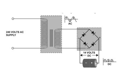
Transformer Rectifier
As shown in the above figure the transformer which has an input of 240 V, steps down the voltage and gives it to the rectifier unit as input.
Transformer Principle
It works based on the principle of Faraday’s Law of electromagnetic Induction. When the Primary windings, which are connected to supply are excited with AC source, they create an alternating flux which links the primary winding. The same primary alternating flux links to the secondary winding by passing through the core of the transformer.
The core forms the magnetic path for the flux to flow from primary to secondary. When the flux links the secondary winding, secondary emf is induced. This is called mutual induction. Based on a number of turns on secondary winding, the magnitude of induced emf is determined. The transformer emf equation is given by
E=4.44∅Nf
As can be seen from the equation, the induced emf is proportional to a number of turns, frequency, and flux. It is to be remembered that, the transformer is constant power, constant flux, and constant frequency device. Hence, the induced emf is directly proportional to a number of turns. The ratio of induced EMFs on primary and secondary is also known as the turns ratio. The same principle is for the induction motor also.
E1/E2 =N1/N2 =k
Rectifier Principle
The rectifier is a static device which converts fixed AC to variable DC. The input alternating voltage is converted to DC voltage by the diodes. The circuit diagram for a half-wave rectifier is shown below
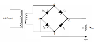
Full Wave Rectifier
As shown in the circuit diagram, four diodes are used to convert AC to DC. Such a circuit is called full-wave rectifiers. The operation of the rectifier can be classified into two modes.
Mode 1: In this mode, i.e. during the positive half cycle of the supply voltage, Diodes D1 and D2 conduct at the same time. The path of conduction for this cycle is A-D1-Load-P-D2-B. During this mode, the first half of the output voltage (as shown in figure 1) is obtained. The load is taken as a resistive load.
Mode 2: In this mode, i.e. during the second half cycle of the supply voltage, diodes D3 and D4 conduct at the same time. The path of conduction for this cycle is B-D3-Load-P-D4-A. During this mode, the second half of the output voltage as shown in figure 1 is obtained.
In one full cycle, we obtain two positive pulses, for this reason, it is called a full-wave rectifier. Instead of two positive pulses, If we have obtained on pulse per cycle, it would have been called as a half-wave rectifier. Similarly, we have a single-phase and three-phase rectifier also. A mobile charger is one of the common days today examples of a rectifier that converts AC to DC for charging mobile.
If the devices used in the rectifier unit are diodes, it is classified as an uncontrolled rectifier. In an uncontrolled rectifier, we cannot control the magnitude of converted DC voltage. Only we obtain fixed DC from fixed AC. Moreover, if we used devices like Silicon Controller Rectifier (SCR) or other devices belonging to the thyristor family, then it is classified as a controller rectifier. We can control the output DC voltage by varying the firing angle of the thyristors. They are also known as phase-controlled rectifiers. Together, the transformer and rectifier form the transformer rectifier unit (TRU). Hence this unit can, step down the input AC supply voltage and convert it into DC for further use.
Halfwave Rectifier Transformer
In the half-wave rectifier transformer unit, the input AC voltage is stepped down to AC voltage based upon a number of turns. The stepped-down AC voltage is converted to DC by using a half-wave rectifier circuit. The difference between half-wave and the full-wave rectifier is
- In the full-wave rectifier unit, four diodes or SCRs are used, but whereas in the half-wave rectifier unit, only one diode is used.
- In the half-wave rectifier unit, we obtain one pulse per cycle, but whereas in the full-wave rectifier unit, we obtain two pulses per cycle.
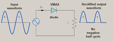
Half Wave Rectifier
As shown in the figure, the input supply voltage is converted to pulsed DC by using a single diode. It won’t have any negative cycle. Since the number of diodes used is less, a half-wave transformer unit is less costly than a full-wave transformer unit. The efficiency and the average output voltage are high for the case of the full-wave transformer unit as compared to the half-wave transformer unit.
The ripple factor, power factor, form factor, etc. are less for a half-wave rectifier unit as compared to the full-wave rectifier unit.
Features of Transformer Rectifier Unit
Other features of the transformer rectifier unit include the following.
- It is available with an air cooling facility. Cooling is essential for proper heat dissipation.
Since the input is given from the transformer, tapings can be provided from the output side for voltage regulation. - The unit can be controlled with remote or SCADA. Recent technologies even include IoT based transformer rectifier units.
- Because of the transformer, it is long-lasting and less maintenance.
- Since we have a full rectifier as an output unit, the full-wave rectifier consists of a lot of harmonics, since output waveforms are not symmetrical. Therefore, transformer rectifier units are also harmonic filtering blocks.
- The range of output voltage varies from 30V-110V DC. Generally, we have more number of applications based on low voltage DC i.e. 30 V.
- The range of output current can vary from 10 A to 40 A.
Transformer Rectifier Applications
As mentioned before, due to its rugged nature, it has a number of applications. A few of them have been shown below
- Aircrafts used for military purpose
- Industries
- Helicopters for military purpose
- Laboratory applications
FAQs
1). Does the transformer rectifier unit provide an AC output voltage?
No, the transformer rectifier unit provides DC output voltage.
2). Does the input to Transformer rectifier unit is DC?
No, the input to the transformer rectifier unit is AC
3). Does the transformer rectifier unit step up the input voltage?
No, the transformer rectifier unit, steps down the input voltage and then converts to DC.
4). Can the transformer rectifier unit be used as a battery?
Yes, the transformer rectifier unit can be used as a battery. Since the output voltage is DC
5). Can the transformer rectifier unit work on DC supply?
No, the input to the transformer rectifier unit must be a DC supply
Hence, we have seen how does a transformer rectifier unit working its applications. Due to the conversion of AC voltage to DC, this unit has a number of applications and versatile in nature. Further, the output DC voltage can be connected to chopper i.e. DC-DC converter and hence we can obtain regulated DC voltage. And by varying the firing angle of the unit, DC voltage of different magnitudes can be easily obtained. This particular device has numerous applications in the aviation industry. Here is a question for you, what is the overall efficiency of the transformer rectifier unit considering the fact that the transformer is one of the most efficient devices, while the rectifier has low efficiency?