A transformer is a stationary electrical machine mainly used to change electrical power from one circuit to another without varying the frequency. Transformers mainly increase or decrease the voltage with an equivalent increase or decrease within the current. The transformer works on the principle of mutual induction occurrence between two transformer windings connected through the common magnetic flux. Transformers are classified into different types based on the construction, power supply, usage, purpose, and cooling used. This article discusses one of the types of transformer based on the power supply type used namely single phase transformer.
What is a Single Phase Transformer?
A transformer that works on single-phase power is known as a single-phase transformer. This transformer is used used to increase or decrease the levels of voltage between two circuits. This transformer includes a magnetic iron core and copper winding where a magnetic iron core works as a magnetic part whereas copper winding works as an electrical part. A single-phase transformer has very low losses because of no mechanical friction involved in its operation.
The principle of single phase transformer is based on Faraday’s induction law of the Electromagnetic principle. Usually, the mutual induction between the primary & secondary windings is responsible for the transformer working within a transformer. These transformers are almost used in all electrical networks where the rating of these networks ranges from low to high voltages. They perform with AC only since DC does not generate any electromagnetic induction.
Construction
A single-phase transformer includes many parts but the core & windings are the main parts. There are many other parts in the construction of a single-phase transformer. So this transformer can be constructed with these two parts with insulation.
Single-Phase Transformer Construction
Core
This transformer’s core is normally made with two materials like silicon steel and cold-rolled grain-oriented steel. The silicon steel material is mainly used to decrease hysteresis losses whereas with CRGO, the highest flux densities can be attained and this material decreases the cost & size of the machine. A transformer is practically made with CRGO steel.
The transformer core during construction is coated into thin laminations & insulating materials like varnish as well as impregnated paper are arranged among them to keep away from short circuit situations. Generally, a core in the transformer offers a low reluctance path for the magnetic flux flow within the circuit.
Windings
The winding is the second most significant part of the single-phase transformer’s construction. For a transformer, the copper winding is mostly chosen which is wounded on both the primary & secondary. The primary winding is connected directly to the supply whereas the secondary winding is connected directly to the load.
Single-Phase Transformer Parts
In the construction of a single-phase transformer, there are various other significant parts like transformer oil, bushings, conservator tank, explosion vent, Buchholz relay, tap changers breather through silica gel crystals.
The transformer oil used in single-phase transformers is vegetable oil or mineral oil for two purposes. This oil works like a coolant & also an insulating medium in between the tank & core of the transformer. The color of this oil is pale yellow and it turns black after excessive use,
The conservator tank is a cylindrical metallic drum with airtight. It is used for storing the transformer oil momentarily & lets the transformer expand and contract easily throughout temperature differences.
Buchholz relay is one type of relay activated by a gas mainly used to guard all the internal as well as early faults within a single-phase transformer. Generally, it is mounted in between the major tank as well as the conservator tank.
When the single-phase transformer is breathing then it will have certain moisture that enters into the tank. This moisture content can be absorbed with silica gel crystals which are available within the breather. The fresh silica gel color is blue & after excessive usage, it will change into pale pink color. So the silica gel crystals require to be changed by new ones for more operations.
The bushings in the transformer are used to bring out the LV & HV windings throughout them. Here, the HV & LV windings are decided depending on the length of the bushing. So HV indicates the lengthier bushing whereas LV indicates the shorter bushing.
Tap changer in single phase transformer is used to balance all the voltage changes. These are available in two types load & off-load. If the tapings are altered without separating the transformer from the power supply, then it is known as an on-load tap changer & vice versa known as an off-load tap changer.
An explosion vent in the transformer is used to avoid the extreme supply of hot oil otherwise the transformer will explode. Once these faults occur, hot oil expels out throughout the explosion vent, so the transformer exploding can be avoided.
How Does a Single-Phase Transformer Work?
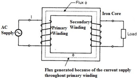
The working of a single-phase transformer is based on the mutual inductance principle. The primary windings in this transformer are connected to an AC provides a supply to the coil so that a magnetic field can be built up this process is called mutual inductance.
The magnetic field which is formed can strengthen once the flow of current throughout the coil enhances and builds magnetic lines of force and it forms the magnetic flux. The secondary winding of this transformer connects the system to the magnetic flux.
In between the two windings of a single-phase transformer, the turn ratio will decide the power of the magnetic field produced. When the current flow increases then the magnetic flux will be increased. The magnetic flux flowing within the core can induce a voltage within the secondary winding. So the induced voltage value can be decided with Faraday’s Law which is determined by
N. dɸ/dt
Where,
‘N’ – the no.of coil turns.
The primary & secondary windings frequency is the same. So the induced voltage will be the same in both windings due to the similar magnetic flux functions to attach these two windings together. In addition, the whole voltage is proportional to the no. of direct turns within the induced coil.
Let’s assume that the windings of the transformer on each side have only a single turn. So current supplies throughout the coil without loss to produce magnetic flux and also 1-volt voltage is induced within the secondary winding.
Here the magnetic flux will be changed sinusoidally because of the AC supply which is given by ɸ = ɸmax Sin ωt.
The main relationship between the emf-induced ‘E’ within the winding coil of turns ‘n’ can be given by,
E = N (d∅)/dt
E = N x ω x ɸmax cosωtφ
Emax = Nωɸmax
Erms = Nω/√2*ɸmax => 2π/√2 x f x N x ɸmax
Erms = 4.44 fNɸmax
Where,
‘f’ is the frequency within Hz that is given through ω / 2π.
‘N’ is the no. of winding coils.
‘ɸ’ is the flux amount within Webers.
The above equation is the transformer’s EMF equation. The EMF for the transformer’s primary winding E, N will be the no. of NP (primary turns) whereas the no. of turns of the transformer’s secondary winding EMF will be N (NS).
The efficiency of a single-phase transformer is generally between 95 to 99% because it does not contain any rotary parts so it is known as a static device. This transformer’s efficiency can be improved by bringing the two magnetic coils jointly during its construction.
Single Phase Transformer Wiring
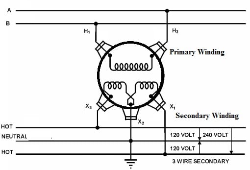
A single-phase transformer wiring diagram is shown below. The two windings of this transformer is shown below. The secondary winding of this transformer is connected in two sections to provide flexibility for the connections. The number of turns & the voltage of every winding are the same. Here the primary leads and secondary leads are represented with (H1, H2) & (X1, X2, X3). So from the top, the primary leads are brought out throughout porcelain bushings whereas the secondary leads are brought out throughout insulating bushings on the tank side where one lead is from the center tap (X2) & one from every end of the secondary coil-like X1 & X3.
Single Phase Transformer Wiring
The typical connection of a single-phase transformer in the following diagram provides a 3-wire service that allows sufficient capacity at least cost. The X2 neutral wire in the center is grounded. A 120V circuit is connected between the neutral & each of the remaining two leads & also a 240V circuit is connected between the two not grounded leads.
Features & Specifications
The features and specifications of the single-phase transformer are discussed below.
- It has an over current protection.
- The transformer fire resistance is helpful within mines.
- This transformer has a sealed side to avoid water intrusion.
- This transformer can be submerged.
- These transformers have low operating frequency ratings.
- The different nominal voltages signify above one primary section.
- The secondary voltage rating determines the range of output voltage.
- The rated o/p current determines the secondary current level.
- Insulating fluid is mineral oil.
- Its frequency is 50 Hz, 60 Hz.
- Its primary voltage is upto 33 kV.
- Its secondary voltage is 120, 210-105, 120/240, 240/480 V, 250.
- Its winding material is copper or aluminum.
- Its capacity is 1KVA.
- Its output voltage is 230VAC.
- Its tapping is 50% and 86.6%.
- Its operating temperature is approximately 0 to 45 Degrees.
- Its power requirement is 220 to 240V AC.
Single-Phase Transformer Problems
1). A single-phase transformer with 50 kVA, 3200/320 V, has iron loss & also full load copper loss of 400 W and 500W correspondingly. So measure the efficiency at half full load & 0.9 power factor and also the load at which point the efficiency is highest.
At any load, the efficiency, as well as the power factor, can be given as
η = (x × kV A × 1000 × p.f)/(x × kV A × 1000 × p.f. + Wi + x2WCu).
= (0.5 × 50 × 1000 × 0.9)/(0.5 × 50 × 1000 × 0.9 + 400 + (0.5)2 × 500).
= 0.976 => 97.6%
The load at the max efficiency is
= Full load kV √Iron Loss/Full Load Copper Loss.
= 50√400/600 => 40.825 kVA.
2). The transformer with A 250 kVA, 11000/415 volts 50 Hz includes 80 turns in the secondary winding. So measure the current for primary & secondary, the number of turns in primary, maximum flux value within the core, and induced voltage or turns on the secondary side.
The current for primary & secondary is
E1I1 = rated kV A * 1000
I1 = 250 * 1000/11000 => 22.72A
E2I2 = rated kV A * 1000
I2 = 250 * 1000/ 415 => 602.4A
The no. of primary turns
E2/E1 = N2/ N1
N1 = E1*N2/E2 => 11000 * 80/415 => 2120
The max flux value can be calculated as;
E2 = 4.44fφmN2
φm = 415/4.44 * 50 * 80 => 23.36mW b
The induced voltage or turn-on secondary can be measured as;
= Voltage within secondary/ Number of turns on the secondary winding
= 415/ 80 => 5.18V
Advantages & Disadvantages
The advantages of a single-phase transformer include the following.
- Single-phase transformers function in parallel and decrease the chance of overloading.
- It has less maintenance.
- This type of transformer can switch ON/OFF depending on the demand of the load.
- These are used for residential purposes.
The disadvantages of single-phase transformers include the following.
- Its maintenance cost is high.
- It occupies more space while installing.
- The fault occurrence will be high whenever one or above the transformer is connected in parallel.
- The transformer protective device is more.
Applications
The uses or applications of single-phase transformers are discussed below.
- The single-phase transformer is mostly used in electronic devices within low-voltage commercial applications.
- This transformer performs as a step-down voltage device to reduce the voltage to the required electronics supply.
- It is used in TV sets for the adjustment of voltage.
- It is used to step up energy within home inverters.
- It is used to provide power to non-urban regions.
- These transformers are used in residential and commercial heating & lighting equipment.
- This transformer is employed in electronic circuits, AC or DC rectifier circuits, and many more.
What are single-phase transformers used for?
The single-phase transformers are used for low-voltage appliances such as home devices, to reduce voltage within local power distribution & voltage regulation within TV sets.
What are the parts of a single-phase transformer?
The parts of single-phase transformers are; the windings like primary & secondary, the core, the yoke & insulation.
What is the single-phase current?
Single-phase current is a two-wire AC power circuit that includes one power, one phase & one neutral wire where the current supplies between the power & the neutral wire. This current is also known as residential voltage because it is frequently utilized within homes.
What is the Transformer “Turns Ratio”?
The transformer turns ratio can be defined as the no. of turns on its secondary winding that can be separated through the no. of turns on its primary winding.
Thus, this is an overview of a single-phase transformer, it’s working, and its applications. This transformer is one type of power transformer that works with a single-phase AC. This transformer gets single-phase AC power & provides single-phase AC. This transformer can be used as a step-down transformer for decreasing the home voltage to a suitable range without changing its frequency. So these transformers are applicable in residential & also commercial light applications. Here is a question for you, what is the function of a transformer?