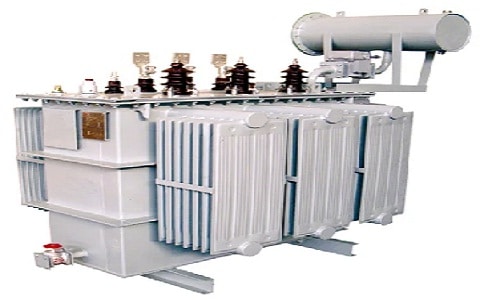
A transformer is normally an electrical device used for increasing or decreasing the voltage supply without changing the frequency of AC between two circuits. Similarly, a transformer that functions with high voltages & currents within the power system network is known as a power transformer. This transformer is used to change bulk electrical energy from one frequency to another. Power transformers are very important devices to transmit, distribute, and usage of electrical power within different sectors. This article discusses an overview of a power transformer, its working, and its applications.
What is Power Transformer?
A power transformer definition is, a type of transformer that is used to transmit electrical power without adjusting the frequency from one electrical circuit to another. So these are utilized for electrical power transmission between generators as well as distribution primary circuits. These transformers step up or step down the voltage within distribution networks. A power transformer’s voltage range varies from 33 kV to 400 kV & above 200 MVA rating. The power transformers with different voltage ratings available in the market are 33 kV, 110 kV, 66 kV, 200 kV, 400 kV, etc. These transformers are frequently used in industrial plants, electrical companies & power plants.

Power Transformer
Power transformers are classified into different types based on the construction of core & winding, turns ratio, phases & core material. Power transformers based on core & winding construction are; berry-type, core-type & shell-type. Power transformers based on turns ratio are; isolation, step down & step up. Power transformers based on phases are; auto, single-phase, and three-phase. Power transformers based on core material are; air core, ferrite core, iron core, and toroidal core transformers.
Features & Specifications:
The specifications of the power transformer include the following.
- This transformer’s rated power ranges from 3 MVA – 200 MVA.
- Primary voltages typically are; 11, 33, 22, 90, 132, 66 & 220 kV.
- Secondary voltages typically are 11, 33, 66 & 132 kV.
- Its rated frequency ranges from 50 – 60 Hz
- It has on-load (or) off-load changers.
- It can be fixed indoors and outdoors.
- The type of cooling is air forced Oil forced cooling.
- Temperature rise is 60 or 65 degrees centigrade.
- Phases are single/three phases.
- It has cooling radiator panels mounted on the tank.
The features of the power transformer include the following.
- These transformers include two types of phases single-phase & three-phase.
- The kVA or Kilovolt-Ampere rating is mainly used for rating a transformer. The kVA rating of the transformer must be greater or equivalent to the load rating. For instance; a 1 KW load needs a 1 kVA transformer.
- This transformer has primary & secondary voltages. The primary voltage is applied to the transformer’s primary winding whereas the secondary voltage is the winding of the coil that provides the output voltage.
- There are four types of coolants that are used to dissipate the surplus heat using the transformer like Oil Natural Air Natural, Oil Natural Air Forced, Oil Forced Air Forced & Oil Forced Water Forced.
- These transformer dimensions include two significant factors the window height & the window width.
- This transformer includes an H terminal & X terminal. So H terminal indicates high voltage whereas the X terminal indicates low voltage.
- This transformer has a serial number format that is used to recognize the year, month, date, and place of manufacturing.
- Power transformers are bulky because of their large size iron core.
- This transformer has a single-tapped winding similar to an autotransformer.
- These have laminated cores for decreasing eddy current losses.
- These are wounded with thick conductors to minimize the series resistance.
- They are built with carefully chosen insulation suitable to the voltages applied.
- These transformers are arranged in such a way that the thermal losses within the core & windings do not cause overheating.
- The flux path must be short for decreasing leakage flux & required energy.
- It operates with a large amount of current.
- The power transformer core is shaped either by a core type or a shell type. The windings in the shell type are arranged on the central limb while the core type includes windings on separate lags.
Construction
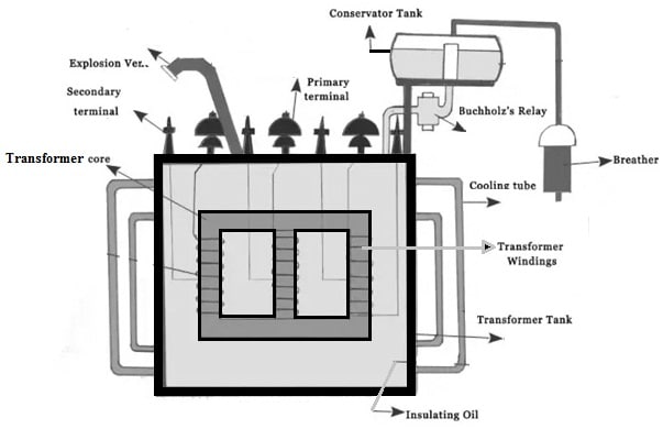
The power transformer construction is shown below. This transformer is constructed with different components like an explosion vent pipe, core, windings, conservator tank, Buchholz relay, breather, cooling tube, transformer tank, insulating oil, etc.

Construction of Power Transformer
Explosion Vent Pipe
This is also known as a pressure relief pipe. The explosion vent function within a power transformer is to avoid injury to the transformer tank from any extreme pressure produced within the transformer.
Core
The core is the center of a power transformer and it is an iron block that works as a path for the magnetic flux flow. Therefore, the core of this transformer can form the magnetic circuit which is utilized to confine the flux to an exact path. Thus transformer core works like the housing for the windings of the power transformer to provide a path mainly for the magnetic flux.
Windings
Transformer windings can be formed with different copper coil turn bundles wherever each bundle can be connected to shape a winding. These windings mainly depend on the supply or the voltage range. Transformer windings are two types such as primary & secondary winding. The primary winding receives electrical energy from the power source while the secondary winding transmits energy to the electric load.
Conservator Tank
The conservator tank of the power transformer is a cylindrical tank that is located on the roof of the transformer’s main tank. The main function of this is to provide sufficient space for the growth of oil in this transformer. It also performs as a reservoir mainly for insulating the oil of the transformer.
Buchholz Relay
A Buchholz relay on a power transformer is a security device equipped with a conservator which is also known as an exterior overhead oil reservoir. These relays can be used as protective devices because they are responsive to the dielectric failure effects that occur in the equipment they defend.
Breather
A breather is one kind of accessory that is connected to the conservator tank in a power transformer. The breather includes silica gel crystals which contain a marvelous capability for moisture absorption. They serve as breathing points mainly for the power transformer.
Cooling Tube
Cooling tubes in the power transformer are welded by the tank mainly for cooling purposes. The insulating oil works as an insulation medium mainly for core & windings. It is also utilized to absorb the heat within the core & windings.
Transformer Tank
The transformer tank is mainly used to protect, hold, and cool the core & winding in a single Electrical distributor transformer. Here, the transformer’s tank simply provides isolation of oil & the core from the external surroundings.
Insulating Oil
Insulating oil in the transformer or transformer oil is stable at maximum temperatures which has outstanding electrical insulating properties. So, it is utilized in some kinds of high-voltage capacitors, wet transformers filled with oil, fluorescent lamp ballasts, circuit breakers, high-voltage switches, etc.
Working Principle
Power transformer works on the principle of Faraday’s electromagnetic induction law. This law states that whenever a closed-loop is brought close to a fluctuating magnetic field, then an emf or electromotive force can be induced across it. So this law is applicable to all inductors, transformers, solenoids, generators, and motors.
Whenever AC is allowed to supply throughout a coil, then an alternating (or) fluctuating magnetic flux surrounds the primary winding or coil of the transformer. The magnetic flux which is produced by the coil passes to a secondary winding effectively throughout a ferromagnetic core. After that, the magnetic flux will induce an electromotive force within the secondary winding because of the electromagnetic induction. So, the emf induced will excite the current flow within the secondary winding.
Difference between Power Transformer and Distribution Transformer
The difference between a power transformer and a distribution transformer includes the following.
| Power Transformer | Distribution Transformer |
| A transformer with an extremely high MVA rating used for transmitting high power at a high voltage level from the power lines to the distribution centers is called a power transformer. | A transformer that is used within the power system close to the load points to step down the high voltage to the usable voltage is called a distribution transformer. |
| The power transformer’s function is to increase the voltage level from low to high for the purpose of transmission. | The distribution transformer’s function is to reduce the voltage supply to the level of voltage demanded by the load of the consumer. |
| The power transformer voltage ratings are; 33 kV, 220 kV, 132 kV, 66 kV, 440 kV, and voltage ratings. | The distribution transformer voltage ratings are 66 kV, 11 kV, 33 kV, 120 V, 110 V & 440 V. |
| The efficiency of the power transformer is maximum at full load. | The efficiency of the distribution transformer is maximum at 60% – 70% of the load. |
| These transformers are fixed within the power system’s transmission section. | These transformers are fixed on the poles close to the load centers. |
| Both the windings of this transformer are connected simply in the delta. | The primary winding in this transformer is connected in the delta whereas the secondary winding is connected in the star to provide a neutral point for single-phase purposes. |
| The power transformer size is larger. | The distribution transformer size is smaller. |
| These transformers function during the load periods only. | These transformers function during the load & no load periods. |
| These transformers are detached throughout the light load periods. | These transformers stay connected throughout the light load periods. |
| It has a high flux density. | It has low flux density. |
| These transformers have high leakage reactance. | These transformers have low leakage reactance. |
| The voltage regulation in this transformer is not a significant parameter. | This transformer has good voltage regulation. |
| The insulation level is high for this type of transformer. | The insulation level is low for this type of transformer. |
| These transformers have higher iron losses. | These transformers have lower iron losses. |
How to Select a Power Transformer?
The selection of a power transformer can be done based on different factors like ratings, taps, connection symbols, impedance, termination arrangement, cooling, fitting, and accessories which are discussed below.
Ratings
The ratings of power transformers mainly include kVA rating, actual system voltage, no-load voltage ratio & frequency. For this transformer, the kVA rating must be chosen from the particular standard ratings according to the requirements. The no-load voltage must be above 5 percent of the actual voltage to pay off the regulation of the transformer partially. The no-load voltage ratio is required to operate the transformer with others in parallel.
Connection Symbol
The connections chosen for the power transformer for up to 66kV are delta/star & star/star. The connections preferred for high voltages are star/delta or star/star.
Taps
On the high voltage side of the transformer has OLCTs or on-load taps chargers where system conditions demand. In OLCT, the number of taps must be sixteen in 1.2 5 steps Once off-circuit taps are specified they must be in the range & provided above the HV side.
Cooling
The cooling type may be ONAN, ONAN or ONAF, ONAF/ONAN/OFOF (or) OFWF based on voltage class within kV and kVA or MVA rating.
Arrangement of Termination
Both terminals of the transformer may be cable boxes, bus trunking, or bare bushings based on the installation technique. For up to 33kV transformer, porcelain bushings & for 66 kV or above transformer, condenser or oil-filled type bushings must be specified.
Impedance
The impedance of the power transformer is decided by taking into consideration of the voltage dip & the secondary levels of fault.
Applications of Power Transformer
The use of power transformers includes the following.
- The power transformer is used in electrical power networks to reduce the power loss in transmission lines.
- These are used throughout step down & step up a high voltage.
- They help in reducing power loss throughout power transmission.
- These transformers are used when a full-capacity load is necessary.
- These are used in the generation & distribution of electric power.
- These transformers are utilized in earthing transformers, isolation transformers, pulse rectifier transformers, wind farm transformers & solar PV.
Power Transformer Failures:
Power transformers, being critical components in electrical power systems, can encounter various issues. Here are some common problems faced with power transformers:
- Overheating: Overheating can occur due to excessive loading, inadequate cooling, or insulation breakdown. It can lead to insulation degradation, accelerated aging, and even transformer failure. Monitoring temperature and ensuring proper cooling are crucial to prevent overheating issues.
- Insulation Failure: Insulation failure can result from aging, thermal stress, electrical stress, moisture ingress, or manufacturing defects. Insulation breakdown can lead to short circuits, winding faults, and reduced transformer performance. Regular insulation testing and maintenance are necessary to prevent insulation-related issues.
- Winding Faults: Winding faults, such as short circuits, open circuits, or turn-to-turn faults, can occur due to mechanical stress, insulation breakdown, or external electrical faults. Winding faults can result in loss of power, abnormal heating, and even catastrophic failures. Regular inspections and testing are essential to detect winding faults early.
- Core Issues: Core issues can arise from core insulation degradation, core lamination damage, or improper core grounding. These issues can affect the efficiency, performance, and magnetic properties of the transformer. Adequate maintenance and regular core testing are necessary to address core-related problems.
- Oil Contamination: Power transformers often use insulating oil for cooling and electrical insulation. Oil contamination due to moisture ingress, chemical degradation, or external pollutants can lead to reduced dielectric strength, insulation breakdown, and corrosion of transformer components. Regular oil analysis and filtration are essential to maintain oil quality.
- Mechanical Vibrations: Mechanical vibrations, such as those caused by unbalanced forces, loose connections, or structural issues, can impact the performance and lifespan of a power transformer. Excessive vibrations can lead to winding displacement, insulation damage, and increased stress on internal components. Adequate mechanical design and regular inspections can help mitigate vibration-related problems.
- Harmonic Distortion: Harmonic distortion in the power system can affect the performance and reliability of power transformers. High levels of harmonics can result in increased losses, overheating, increased noise levels, and insulation stress. Proper harmonic filtering and assessment are necessary to minimize the impact of harmonics on transformers.
- Ageing and Degradation: Transformers, like any other electrical equipment, experience aging and degradation over time. This can result in reduced performance, increased failure rates, and decreased reliability. Regular maintenance, condition monitoring, and periodic assessments are crucial to identify and address aging-related issues.
Regular maintenance, periodic testing, and condition monitoring play vital roles in identifying and addressing these issues. Early detection and timely mitigation can help prevent catastrophic failures, extend transformer lifespan, and ensure the reliable operation of power systems.
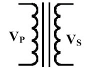
What is a transformer symbol?
The transformer schematic symbol looks like two coils or windings located next to each other, where the magnetic coupling as well as orientation in between these two windings is also specified in its schematic symbol.

Transformer Symbol
What are the two main types of losses in a transformer?
The two main types of transformer losses are; load losses which are associated with the coils whereas the no-load losses which are produced within the core.
Where the power transformer is located?
The power transformer is located in electrical substations, the service entrance to huge buildings otherwise groups of buildings.
What is meant by a power transformer?
The transformer which works with high voltages & currents within the power network system is known as a power transformer.
Thus, this is an overview of a power transformer – construction, working, differences, and applications. A power transformer is used mainly for transmitting electrical energy between the distribution primary circuits & the generator. There are mainly four types of power transformer losses available that affect the transformer’s efficiency like iron or core, copper, stray, dielectric, etc. Here is a question for you, what is an autotransformer?