Electrical transformers ought to have the credit of the most crucial developments in the industrial era along with other discoveries of running water, gaslighting, and steam power. The name indicates that the transformer is used for the conversion of electrical energy from a higher level to a lower level. There are numerous kinds of transformers developed to deal with various voltage levels like a step-down and step up transformer.
As the inventions are enhancing day-by-day, the variations and developments in transformer also take place. As there are many types of transformers, today this article is going to explain on step up transformer, its detailed theory, purpose, advantages, and uses.
What is Step Up Transformer?
A step up transformer is a kind of power distribution transformer where the secondary winding currents are more than the primary winding currents. As the device steps up the voltage level, this is called a step up transformer. It reduces the output current in order to maintain both the input and output power levels as equal.
Whereas the other factors such as nominal power and functional frequency levels are nearly similar on both sides of the windings for the reason that transformer is a very effective one when the voltage and current levels are generally different.
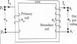
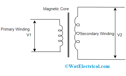
This device provides galvanic isolation for electrical systems and because of these characteristics, a step up transformer holds more importance and provides reliable transmission. The step up transformer diagram is

Step Up Transformer Diagram
Theoretically, a transformer can be functioned as both step-up and step-down and is based on the direction of energy flow. When compared with LV windings, HV windings are more whereas the cross-sectional area of LV winding is more than HV. This is because LV windings hold more current. In general, LV windings are positioned near to the transformer core section and HV windings are wound on it.
This is the basic step up transformer theory.
The formula for turns ratio is given as
n = NP/NS = VP/VS
The above formula states that the turn ratio in a step up transformer has a direct proportion with the voltage ratio. It also shows that there is energy flow from the low voltage side to the high voltage side. The voltage level is stepped up from input to output voltage.
In order to obtain the step up transformer formula for output voltage, the above equation can be re-arranged, and it is given by
VS = (NS * VP)/NP
Construction of Step Up Transformer
A step up transformer construction is so simple. It has few essential parts like core and windings sections. And those parts explained as below:
Core
The core section design can be done by using a high permeable material. Using a core substance in the device allows for the magnetic current flow to have minimal wastage such as eddy current loss because of hysteresis. As the permeability levels of the core are more than air, it restricts the magnetic flux lines across the core substance. Thus because minimal coactivity elements and hysteresis are chosen for the creation of magnetic cores same as ferrite substances and silicon steel. So, the efficiency of the transformer can be augmented by lessening the transformer wastage.
The core section of the transformer can also be wounded in order to keep the eddy current wastage at a lesser value so that the heating of the core can be lessened. When there is the heating of the core, there will be less loss of electrical power, and the transformer’s efficiency might be minimized.
Windings
A step up transformer windings assists in transferring the current that is developed in the transformer. The windings are usually constructed for cooling the transformer and handle the circumstances of testing and functionality. Even though the coil’s density in the primary section is more, it has a lesser number of turns. In the same way, the coil’s density in the secondary section is narrow and has more turns. The design of windings can be done in such a way that the primary section holds minimal energy when compared with the secondary section. The step up transformer symbol is represented as follows:

Symbol
The winding material that is used in the transformer is made of aluminum and copper. As the cost of aluminum is not more when compared with copper less but using a copper material can enhance the life period of the transformer. There exist various kinds of laminations so that minimizing eddy currents waste such as EI or EE kind.
Precautions
- When there is any chance of burning takes place in the device, the power cord has to be quickly removed
- Any kind of metallic substances should not be near the experimental location due to the reason that the device functions as a magnet and it attracts the magnetic devices
- Only the experiments are to be performed under perfect guidance and experience
Working of Step Up Transformer
This section explains the function of step up transformer. In the below-shown circuit, the voltages at input and output sections are given as V1 and V2 and the coil turns at primary and secondary windings are given by T1 and T2. As the coil turns are more at secondary winding, the output value is more at secondary section only. As there is the flow A.C all through the device, then the transformation of current that flows in one direction alters to another direction.
The flow of current tends to generate magnetic flux in the winding area and the direction of the magnetic pole gets altered when there is a change in the path of current flow. There will be the generation of voltage in the secondary winding when it is placed in the vicinity of moving magnetic flux. So that alternating current in the primary section generates a moving magnetic flux and thus voltage generation takes place at the secondary winding.
The crucial purpose of step up transformer is Generator step up which is a GSU component that is used in almost all of the generating plants. These devices hold higher turn ratio values. The generation of voltage at the time of energy production can be enhanced and used for huge distance transmission applications. This produced energy has higher current and minimal voltage values,
As per the data collected from on generating plant, the standard primary value of a GSU device ranges from 6 – 20 kV, whereas the standard secondary value ranges from 110 kV – 410 kV based on the energy transmission network that is connected with GSU secondary section. Based on the typical transformer power, the current value on the primary side is more and it can be in the range of nearly 30000 Amps. This currently seems to be not potential for power broadcasting and it has to be minimized because of transmission power wastages which are RI2. In addition, GSU devices even generate galvanic isolation in between the generator and the electrical system.
Advantages and Disadvantages
The advantages of step up transformer are:
- Step up transformers are mainly used in power transmissions
- These devices have increased efficiency levels and also just with the induction of electricity, the device can be started quickly and it does not need any kind of earlier booting time.
- As step transformers increase the voltage value and lessen the current. This finally reduces the transmission resistance value. So, for huge distance transmissions, these devices are the perfect and less economical choice
- They can be used even for longer time periods
- Also utilized in commercial and residential locations
- As the advancements in technology are progressing, the efficiency levels are also increased, and it nearly provides an efficiency rate of 95%
The disadvantages are:
- As step up transformers are continuously operated, it requires a consistent cooling system and that also needs regular maintenance
- It only operates for alternating current in order to step up the voltage levels. Thus because they are non-operative for direct currents
- The transformer size is huge
Affected Factors
While choosing a step up transformer, there are few factors to be considered because they show huge impact on the device performance and efficiency levels. When the wrong specifications are chosen, this might lead to huge complications. So, the factors are:
- Number of phases present on the primary and secondary windings
- The cooling medium that is used in the device
- The material used for the construction of windings
- Rating levels of the transformer
- Efficiency levels
Applications
The main uses of a step up transformer are explained as follows:
- Utilized in electronic systems such as stabilizers and inverters for the regulation of voltage from low level to high level
- Used for the distribution of electrical energy
- Step up transformers are also applicable for varying high voltage values in transmission networks which are generated from alternators
- Also used for the operation of microwave ovens and electric motors
- Used for boosting electronic equipment
- Huge power setup devices are employed as GSU transformers in order to step up the generated energy to a higher voltage level thus the transformer’s efficiency and performance can be increased
Know more about Step Down Transformer, Types of Losses in a Transformer, Potential Transformer , Three Point Starter.
This is the detailed concept of step up transformer. This article has provided a clear analysis of step-up transformer working, construction, purpose, applications, uses, and its drawbacks. Also, know how to choose the best step up transformer and what are its specifications?